X-Controller Assembly
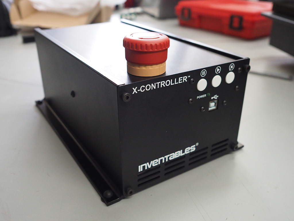
Welcome to the X-Controller assembly instructions! The images shown at the beginning of each step show the finished results of that step. This is to provide context for what you're about to start working on, and offer those eager and willing to figure things out on their own a way to skim through more quickly. Make sure to click on the thumbnails to see more details.
Each step also begins with a bill of materials that details the components about to be used. To avoid any frustration you might have from finding out that something's missing, we've laid out the bill of materials here so you can find out now before you even get going. Click below to reveal the BOM and make sure you received everything correctly. If there's anything missing please contact us at help @ inventables.com for replacements.
Bill of Materials
| SKU | Name | Quantity |
| 01 | Rubber Foot | 4 |
| 02 | Chassis | 1 |
| 03 | Enclosed Power Supply | 1 |
| 04 | Power Supply Interface PCB | 1 |
| 05 | Button Head Cap Screw M4 x 8mm | 6 |
| 06 | Main Controller PCB | 1 |
| 07 | Power Cable | 1 |
| 08 | Ribbon Cable | 2 |
| 09 | E-Stop Cable | 1 |
| 10 | E-Stop Button | 1 |
| 11 | Top Panel | 1 |
| 12 | Buttons PCB | 1 |
| 13 | Threaded Standoff M3 | 4 |
| 14 | Button Head Cap Screw M3 x 6mm | 10 |
| 15 | USB Bulkhead Cable | 1 |
| 16 | Front Panel | 1 |
| 17 | Socket Head Cap Screw M4 x 6mm | 8 |
| 18 | Back Panel | 1 |
| 19 | Flat Washer #4/M3 | 4 |
| 20 | Fan | 1 |
| 21 | Socket Head Cap Screw M3 x 20mm | 4 |
| 22 | Hex Nut M3 | 4 |
| 23 | Terminal Block 4C 5mm Plug | 4 |
| 24 | Terminal Block 8C 3.5mm Plug | 1 |
| 25 | Terminal Block 7C 3.5mm Plug | 1 |
| 26 | USB Cable | 1 |
| 27 | Power Cord | 1 |
Gather up the following tools to get started.
| Tools | ||
| Phillips Screwdriver | ||
| 2.5mm Allen Wrench | ||
| 3mm Allen Wrench | ||
| 5.5mm Open End Wrench (Adjustable Wrench or Pliers) |
Install Power Supply
- Attach Feet
- Prepare Power Supply Power Supply
- Attach Power Supply Interface PCB
- Attach Power Supply to Chassis
| SKU | Name | Quantity |
| 01 | Rubber Foot | 4 |
| 02 | Chassis | 1 |
| 03 | Enclosed Power Supply | 1 |
| 04 | Power Supply Interface PCB | 1 |
| 05 | Button Head Cap Screw M4 x 8mm | 4 |
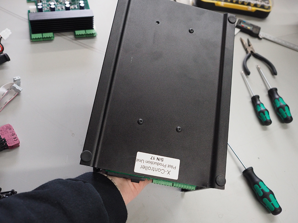
1. Attach Feet (OPTIONAL)
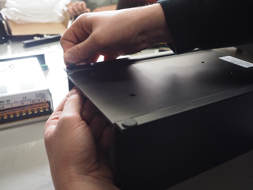
Attach the four rubber "feet" to the bottom of the chassis. Flip the chassis over and twist the foot through the hole. Once the foot is partially in, try using your fingernail to bring it the rest of the way through. This is an optional step and the holes can also be used to mount the chassis to a work table.
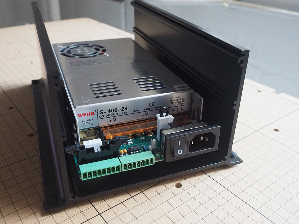
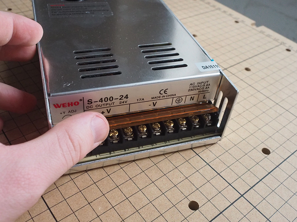
2. Prepare Enclosed Power Supply
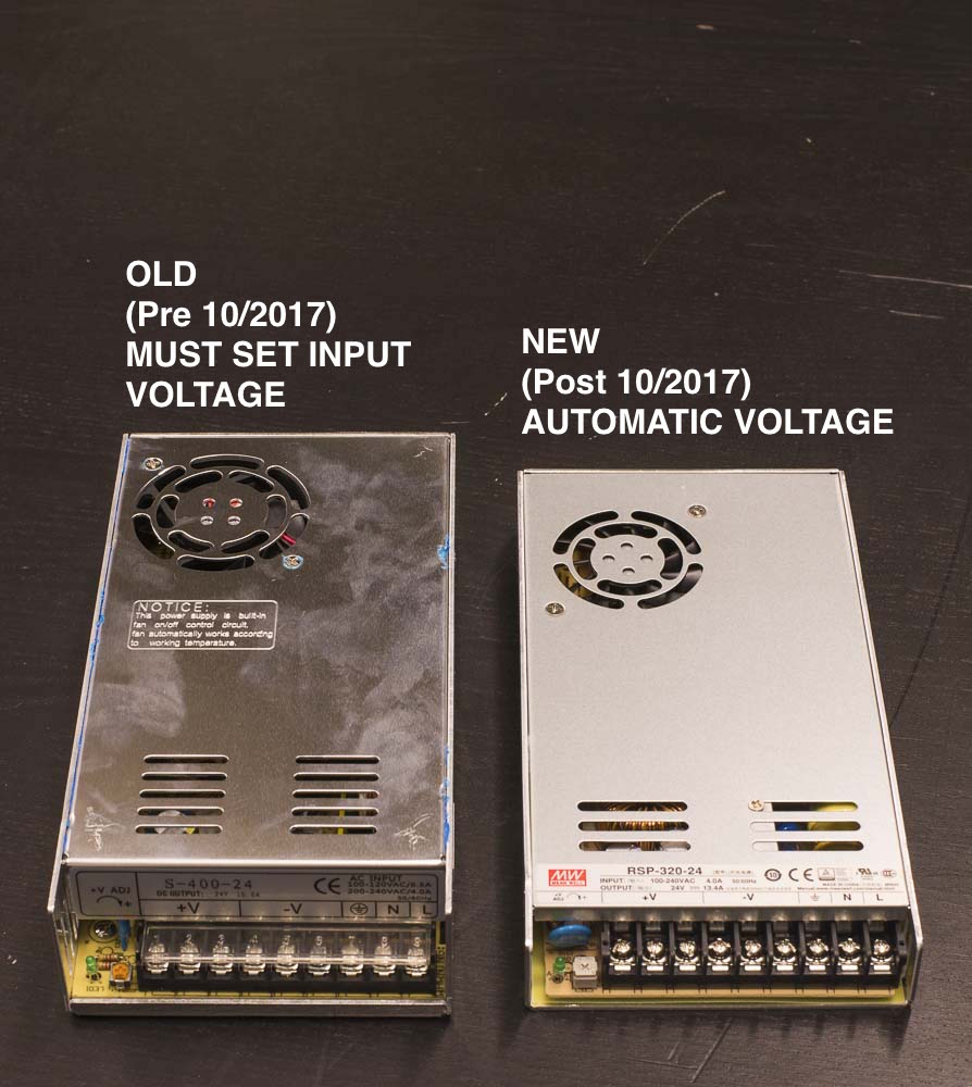
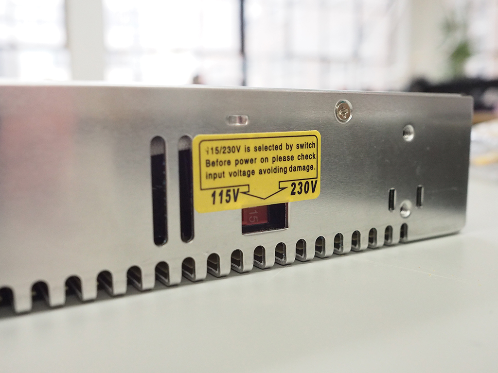
Since approximately October 2017, we are shipping X-Controllers with a new style of power supply that will automatically work with any mains AC voltage between 100V and 240V. The new power supply is also thinner and has a slightly lower nominal wattage, but it is otherwise functionally identical to the old power supply. If you have the old style, flip the toggle switch on the side of the power supply to the voltage that corresponds to your outlet voltage.
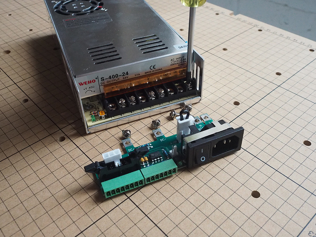
3. Attach Power Supply Interface PCB
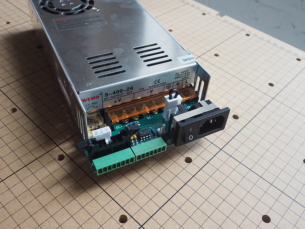
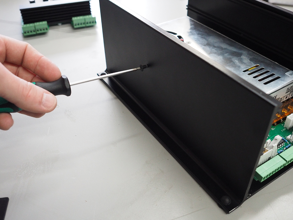
Flip the plastic cover back and remove the screws on the enclosed power supply that correspond to the "fingers" on the power supply interface PCB. Attach the power supply interface PCB and reinstall the screws to secure it in place.
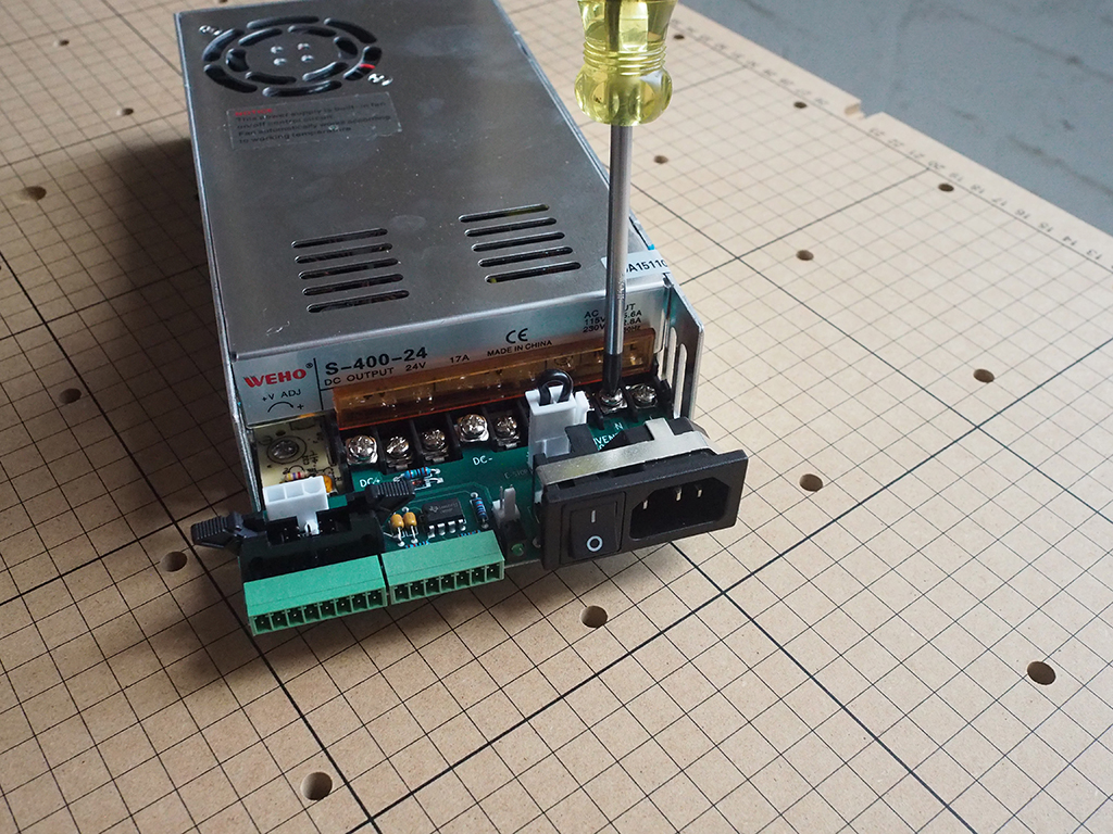
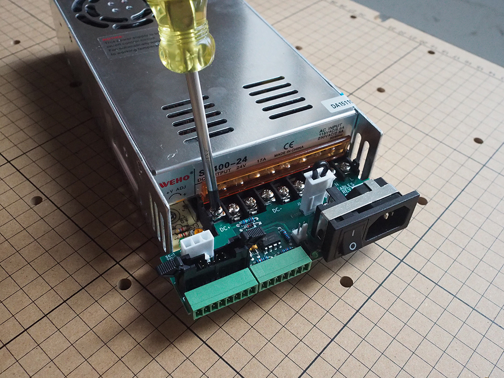
Note: You won't have access to the side of the power supply from here on out, so double check your voltage before moving forward.
4. Attach Power Supply to Chassis
Using the M4 x 8mm button head cap screws, attach the power supply through the mounting holes on the underside of the chassis. The threaded holes on the base of the power supply are delicate, so try not to overtighten the screws when assembling.
Install Controller Board
- Prepare Controller Board (OPTIONAL)
- Attach Stops
- Wire Controller Board
- Attach Controller Board

| SKU | Name | Quantity |
| 05 | Button Head Cap Screw M4 x 8mm | 2 |
| 06 | Main Controller PCB | 1 |
| 07 | Power Cable | 1 |
| 08 | Ribbon Cable | 1 |
| 09 | E-Stop Cable | 1 |
1. Prepare Controller Board
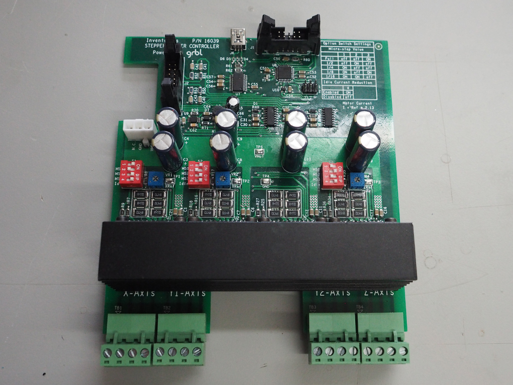
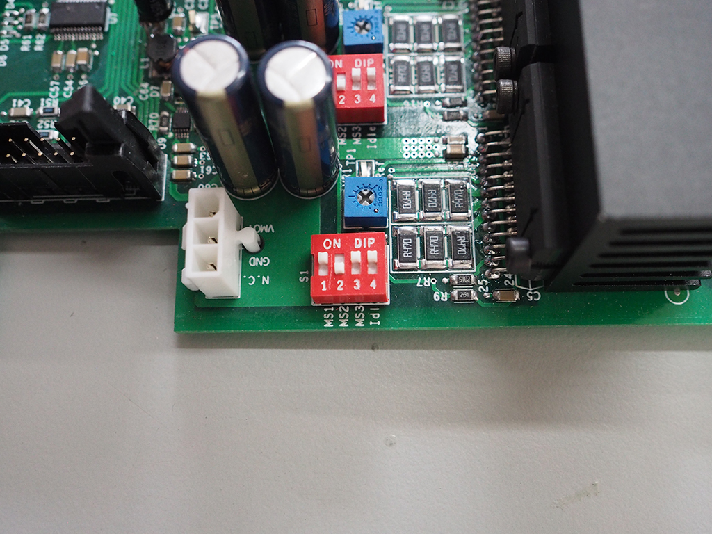
Unless you're an advanced user looking to make some tweaks or want an easy way to use your X-Controller without re-wiring your machine, you won't need to make any adjustments. That being said, in order for the Grbl firmware to know how far the machine will move in reality, a few things need to be set on the controller board. Microstepping is one of these settings and allows the motors to move to positions between normal steps; increasing accuracy and smoothing the motion of the motor. Depending on the capabilites of the motors, there does come a point where the microstepping will no longer increase accuracy. Using high microstep values (e.g 16) can reduce stepper motor torque, so it's best to use the lowest value that can still give you the axes resolution you're looking for. Dip switches on the main controller board allow you to set the microstepping. Make sure to check out the diagram on the board for proper placement of the switches.
Idle current reduction is another feature that can be set on the controller board. This setting automatically reduces the amount of current shortly after the motor stops moving, reducing heat from the driver and the motor. This feature is especially great for the Z axis which spends a lot of its time idle. You can set this using the dip switches, just make sure to again check out the diagram for proper placement.
The potentiometers on the controller board allow you to control the maximum current to the motors. Clockwise increases the current and counter-clockwise decreases the current. Current ratings are different for NEMA 17 (1.6A) and NEMA 23 (2.8A) stepper motors and need to be set accordingly. The slot between the dots on the gray actuator is the pointer, and can be adjusted based on the diagram on the controller board.
For those users who would like to know the current more precisely, you can measure the amount of voltage on the reference and ground test points. Use the formula
on the diagram to determine the current. For example, if you measure 1V you get 2.13 amps.


2. Attach Stops
Install the M4 button head cap screws in the threaded holes on the side of the chassis. These screws locate the back of the controller board and make the face of the board flush with the chassis.
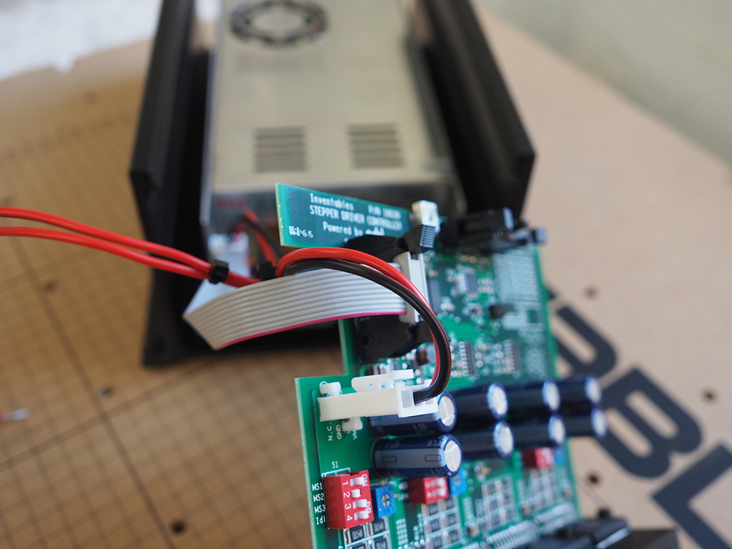
3. Wire Controller Board
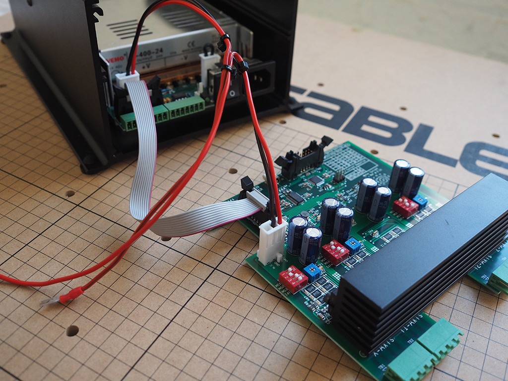
Attach the cables to the power supply interface PCB. The cables can only be connected in one orientation, so if they don't attach well double check them and try again. Try to orient them so that the wires can easily travel from board to board.
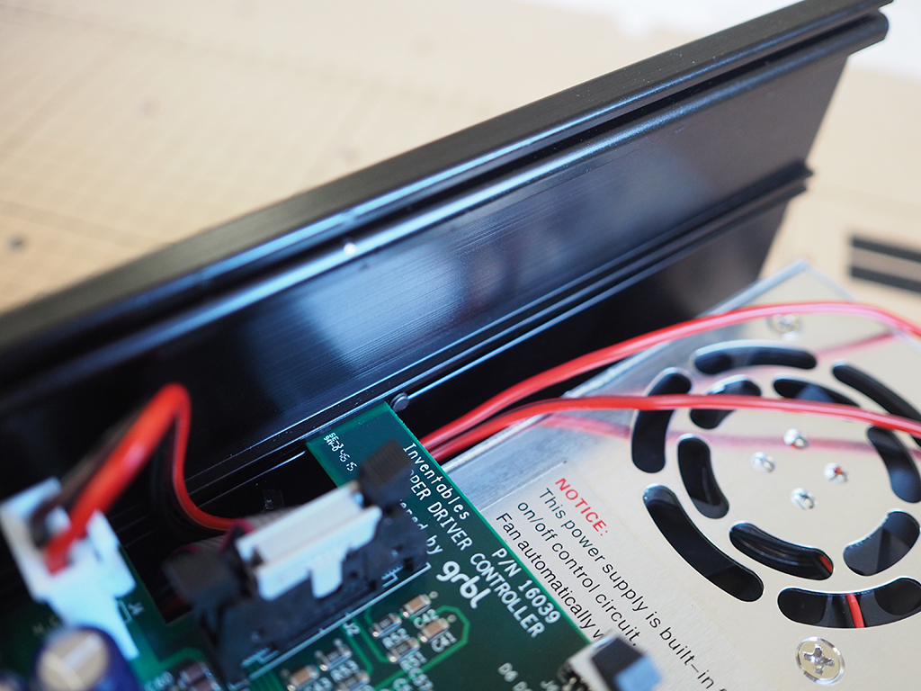
4. Attach Controller Board
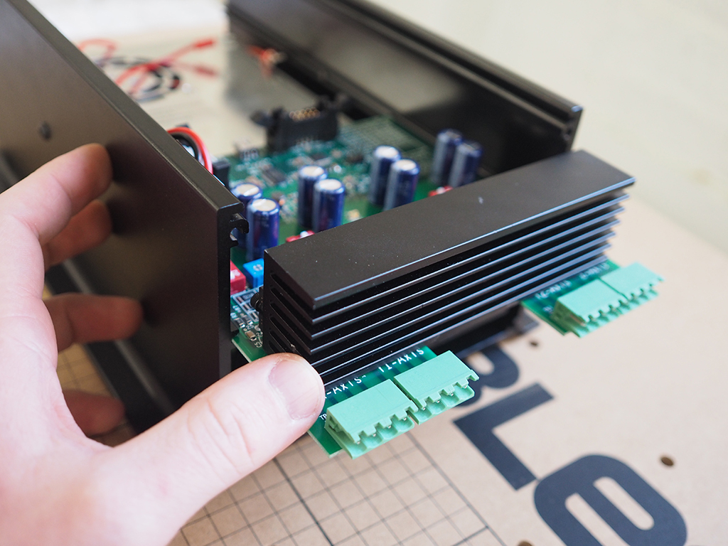
Slide the controller board into the channels of the chassis, making sure you route the wires through the cutout on the board to prevent snagging or pinching.
Install Front Panel
- Dissasemble E-Stop Button
- Attach E-Stop Button
- Attach USB Cable
- Wire E-Stop And Attach Front Panel
| SKU | Name | Quantity |
| 08 | Ribbon Cable | 1 |
| 10 | E-Stop Button | 1 |
| 11 | Top Panel | 1 |
| 12 | Buttons PCB | 1 |
| 13 | Threaded Standoff M3 | 4 |
| 14 | Button Head Cap Screw M3 x 6mm | 10 |
| 15 | USB Bulkhead Cable | 1 |
| 16 | Front Panel | 1 |
| 17 | Socket Head Cap Screw M4 x 6mm | 4 |
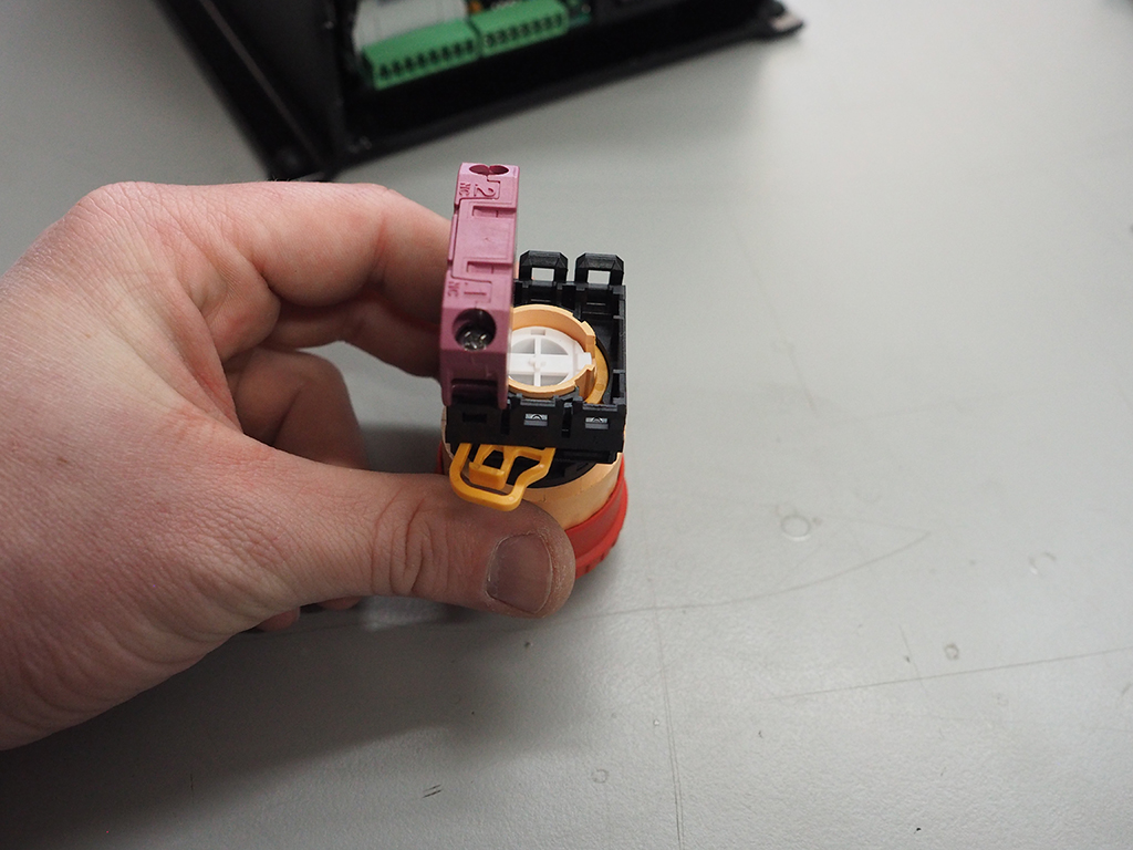
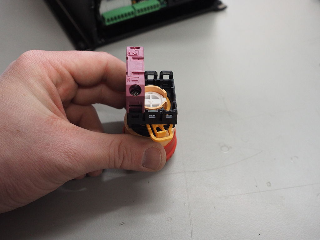
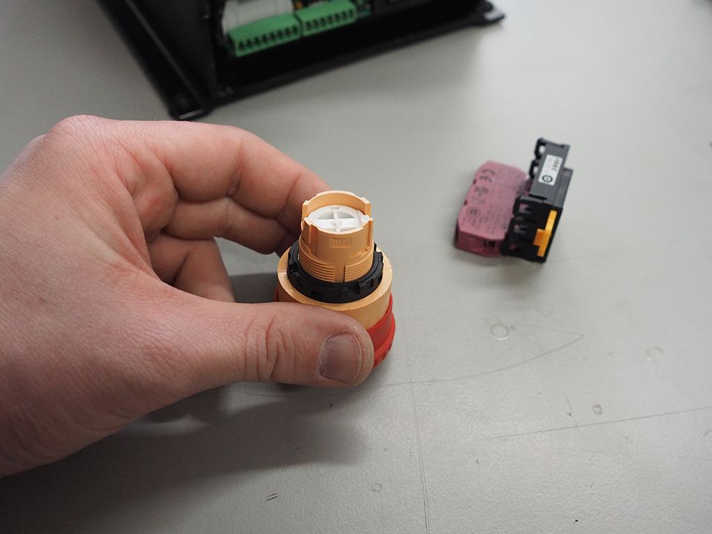
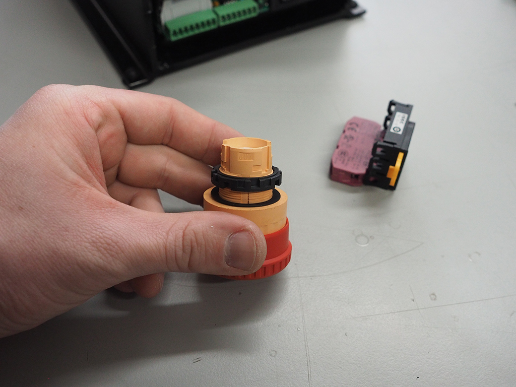
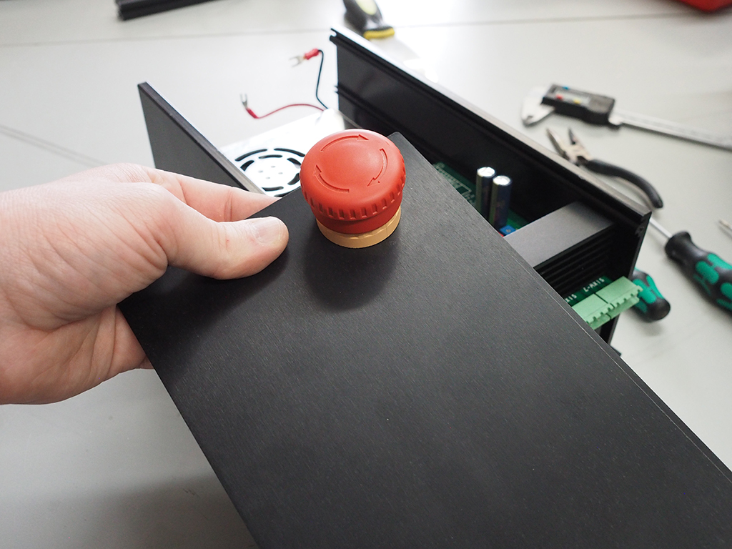
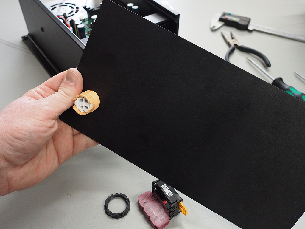
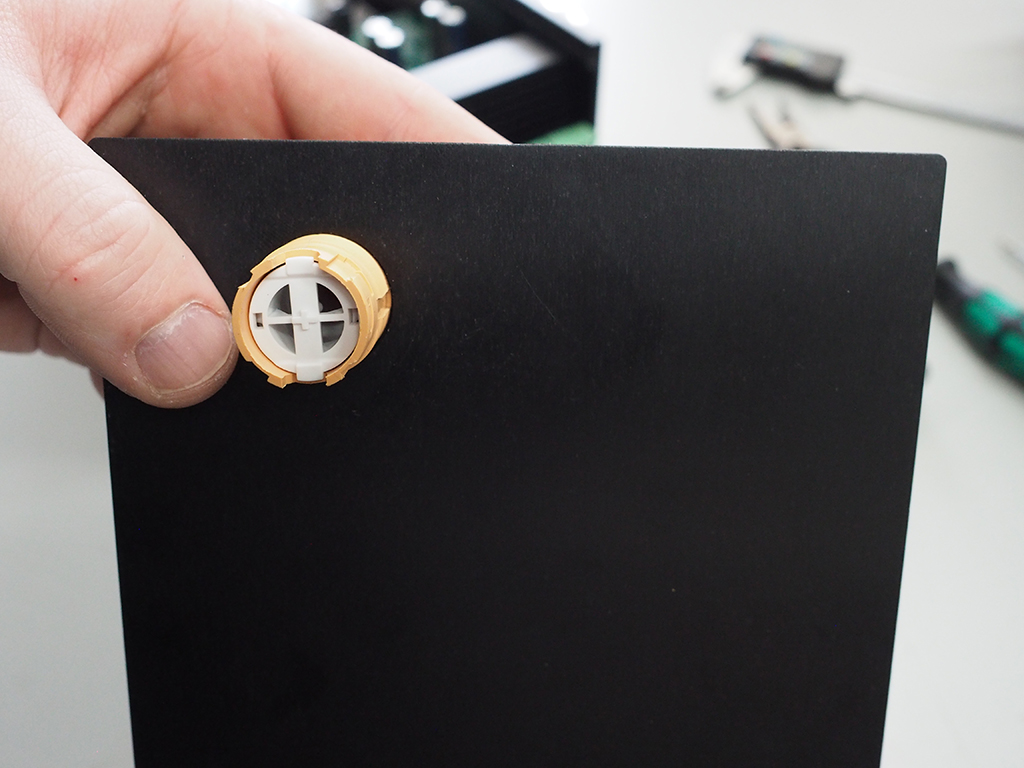
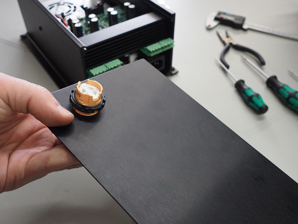
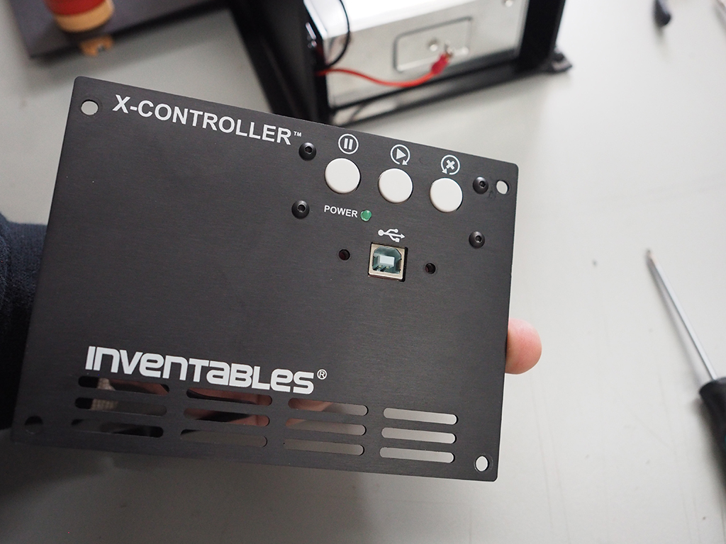
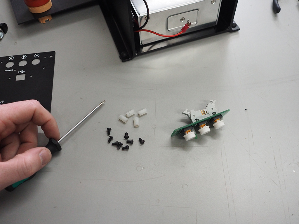
1. Dissasemble E-Stop Button
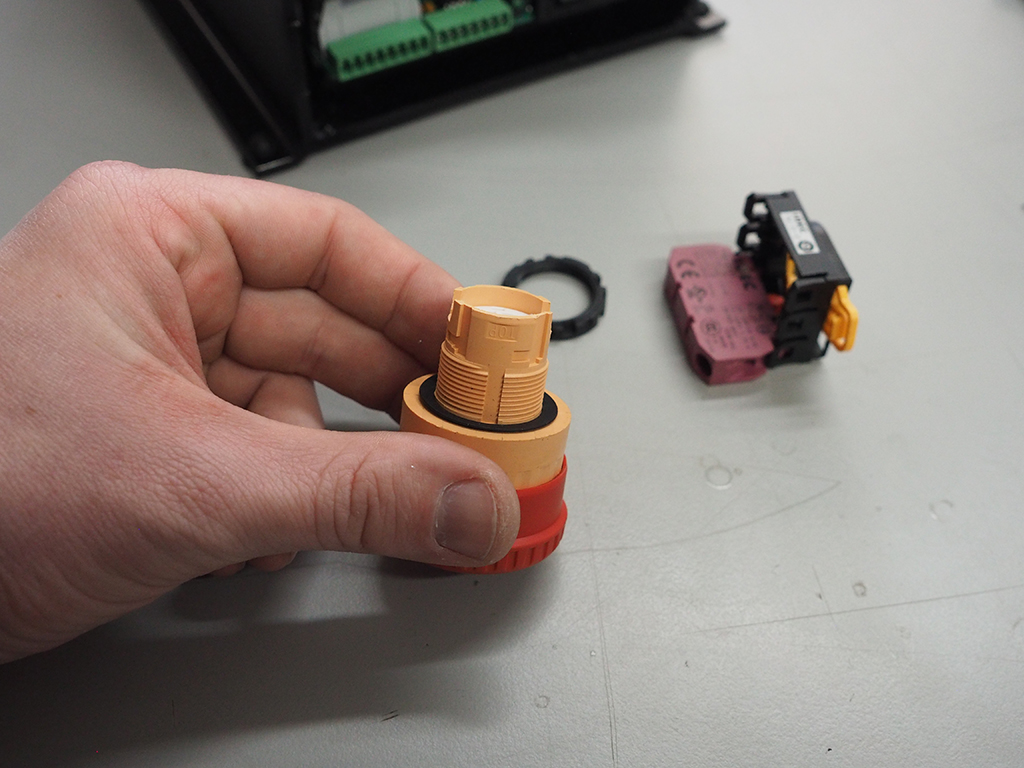
Remove the button from the screw terminals by gently pulling on the yellow tab. With the button upside down (as pictured) pull the tab towards you and then to the right to disengage the two parts. Unscrew the nut attached to the base of the button. This nut will be used to secure the button to the enclosure.
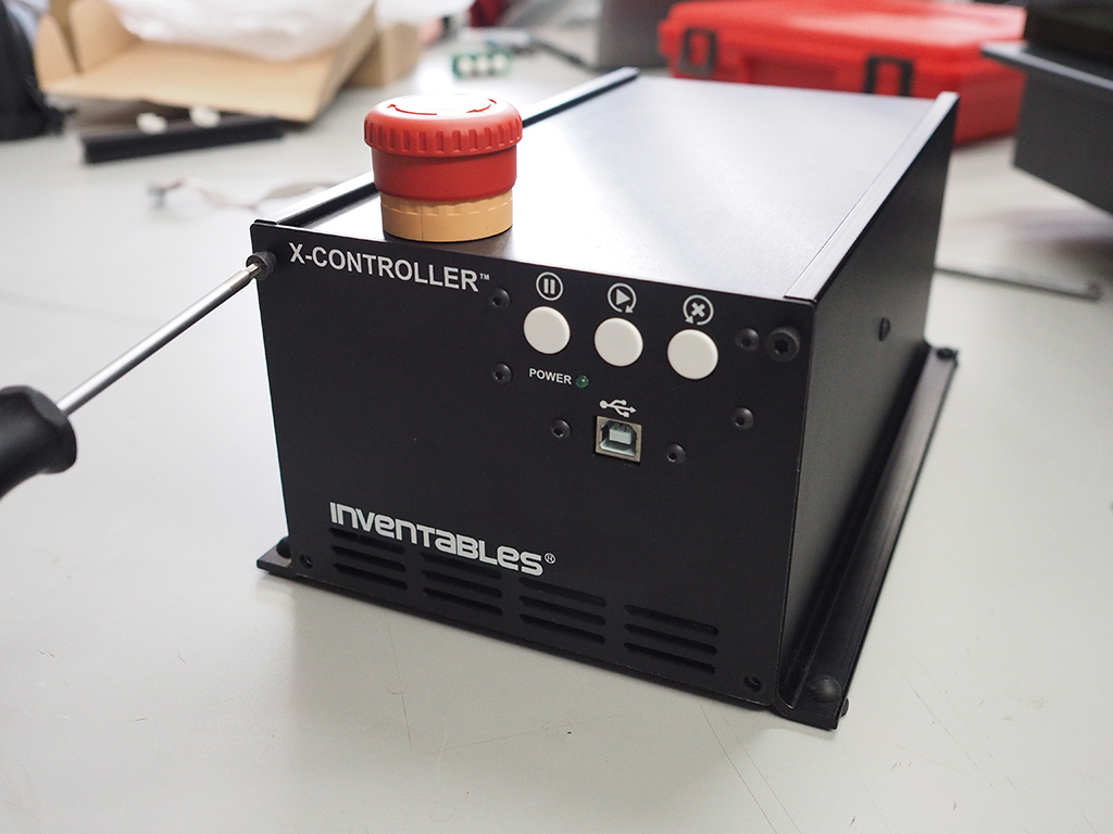
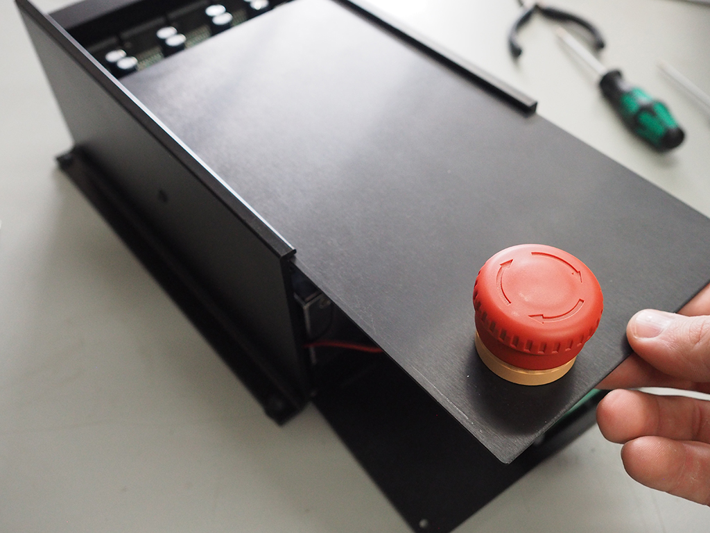
2. Attach E-Stop Button
Insert the button through the hole on the top panel and secure using the nut. Make sure the side of the button marked "TOP" is facing the center of the top panel. Slide the top panel into the channels of the chassis, far enough back so you can access the Mini USB port on the main controller board.
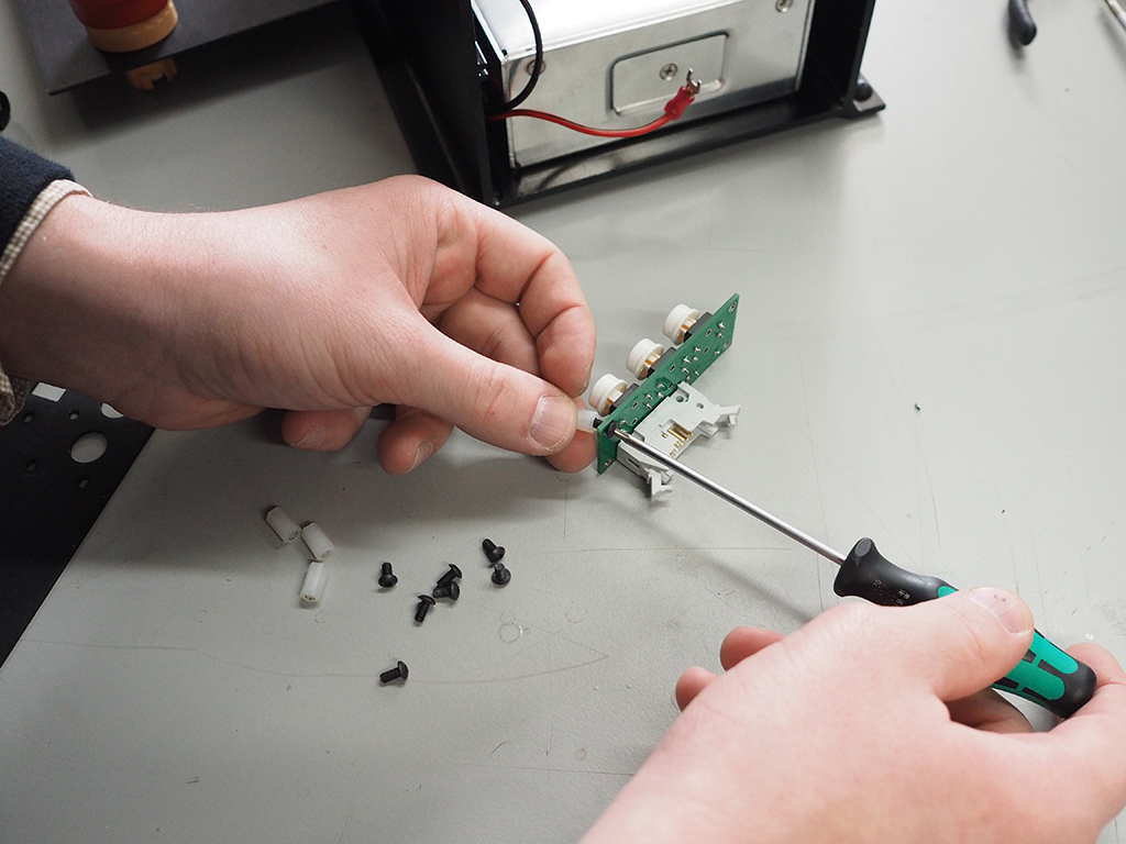
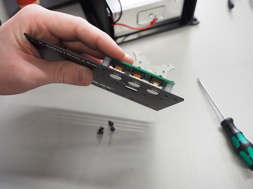
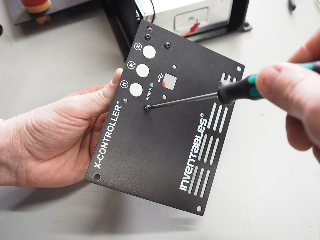
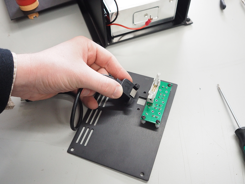
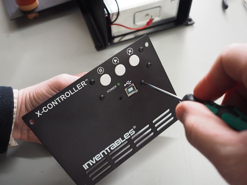
3. Attach Buttons And USB Cable
Using the M3 button head cap screws, attach the USB cable to the front panel. Attach the other end of the USB cable to the main controller board. Don't attach the front panel to the chassis until the rest of the e-stop is installed in the next step.
4. Wire And Attach Front Panel
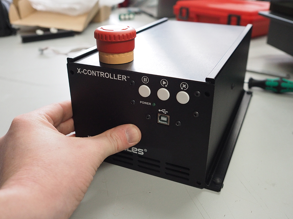
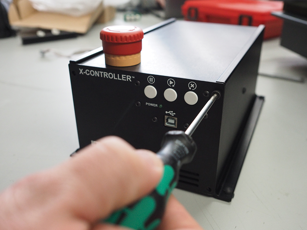
Loosen the phillips head screws on the screw terminals and attach the ends of the e-stop cable to each side of the NC screw terminal as pictured. Tighten the screws on the screw terminals to hold the cable in place. To attach the wired screw terminal to the button, line up the "TOP" marking on the button with the "TOP" marking on the screw terminal. Once in postion, move the yellow tab towards the back of the assembly to lock in place. Attach the front panel using the included M4 socket head cap screws.
Install Back Panel
- Attach Fan
- Wire Fan And Attach Back Panel

| SKU | Name | Quantity |
| 17 | Socket Head Cap Screw M4 x 6mm | 4 |
| 18 | Back Panel | 1 |
| 19 | Flat Washer #4/M3 | 4 |
| 20 | Fan | 1 |
| 21 | Socket Head Cap Screw M3 x 20mm | 4 |
| 22 | Hex Nut M3 | 4 |
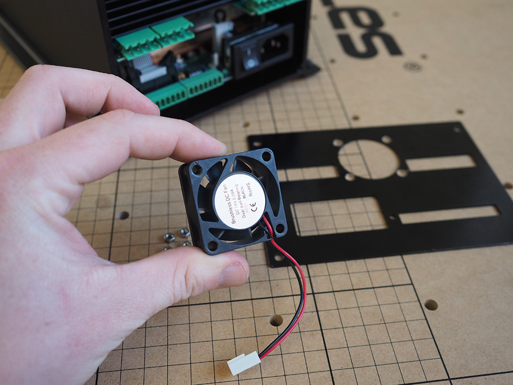
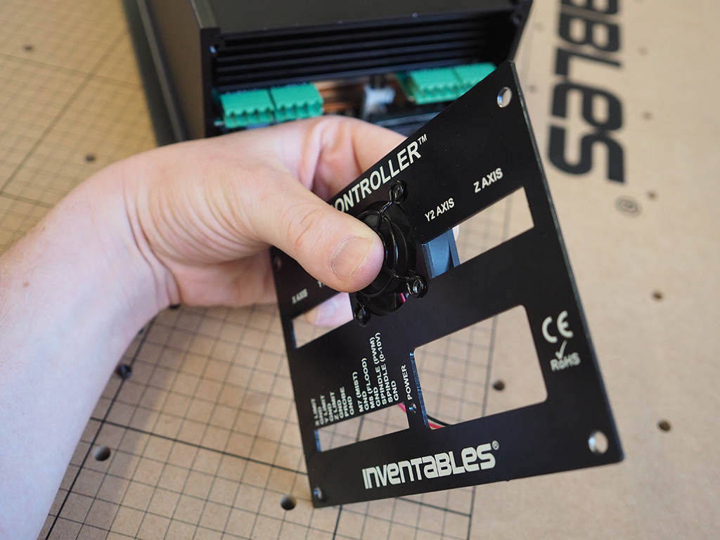
1. Attach Fan
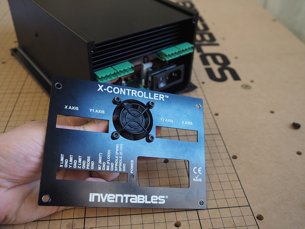
Using the included M3 socket head cap screws, nuts, and finger guard, attach the fan to the front panel with the wires pointed down.
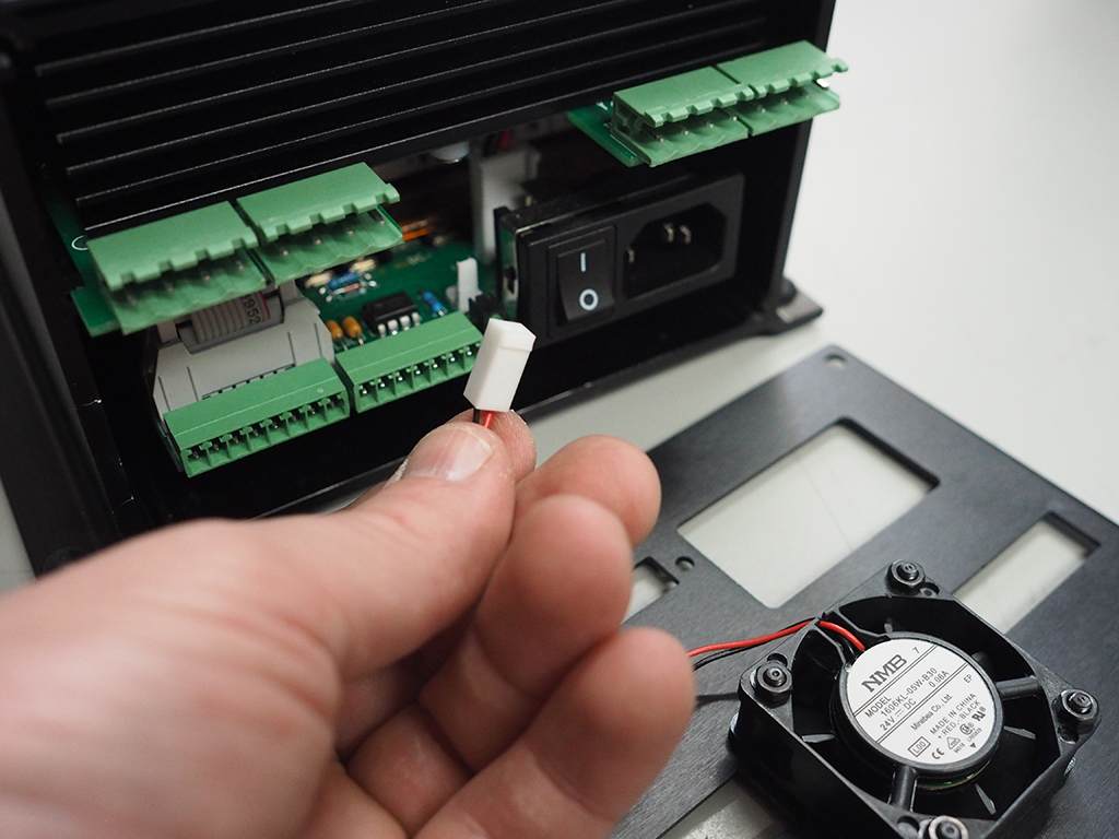
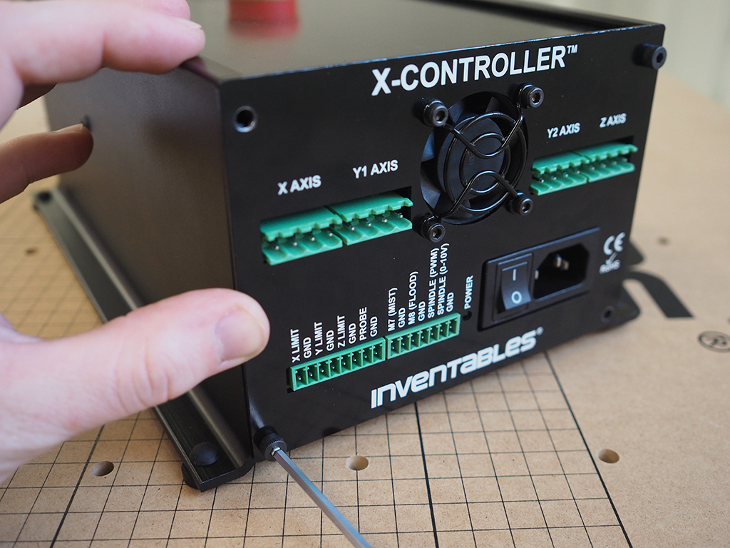
2. Wire Fan And Attach Back Panel

Attach the fan cable to the power supply interface PCB. The cable can only be connected in one orientation, so if it doesn't attach well double check and try again. Check the ribbon cable connector at the power supply interface PCB and attach the back panel using the included M4 socket head cap screws. You may need to wiggle the lower PCB in place when installing to have the back panel flush with the chassis.
SERVICE INFORMATION:
If any repairs need to be made to your X-Controller, make sure everything is unplugged and powered down before you do anything at all. Failure to do so may cause damage to your X-Controller internals.Next Step: Usage