Wide Makerslide
Note: In these photos, we will be installing the wide MakerSlide on a 500mm sized X-Carve, circa 2015. Some of the exact parts on your machine will be slightly different, but you should still use these instructions to get the general idea of what steps are necessary to swap our your x-axis gantry with the wide MakerSlide rail.
During this process, you will need access to all sides of your machine in order to install the new wide MakerSlide rail. To make it easier to access all sides of the machine, we have removed our stepper motor wires from the microcontroller and unplugged the DeWalt router from the wall. Make sure you can easily see and access the back of your x-carriage and the two y-plates.
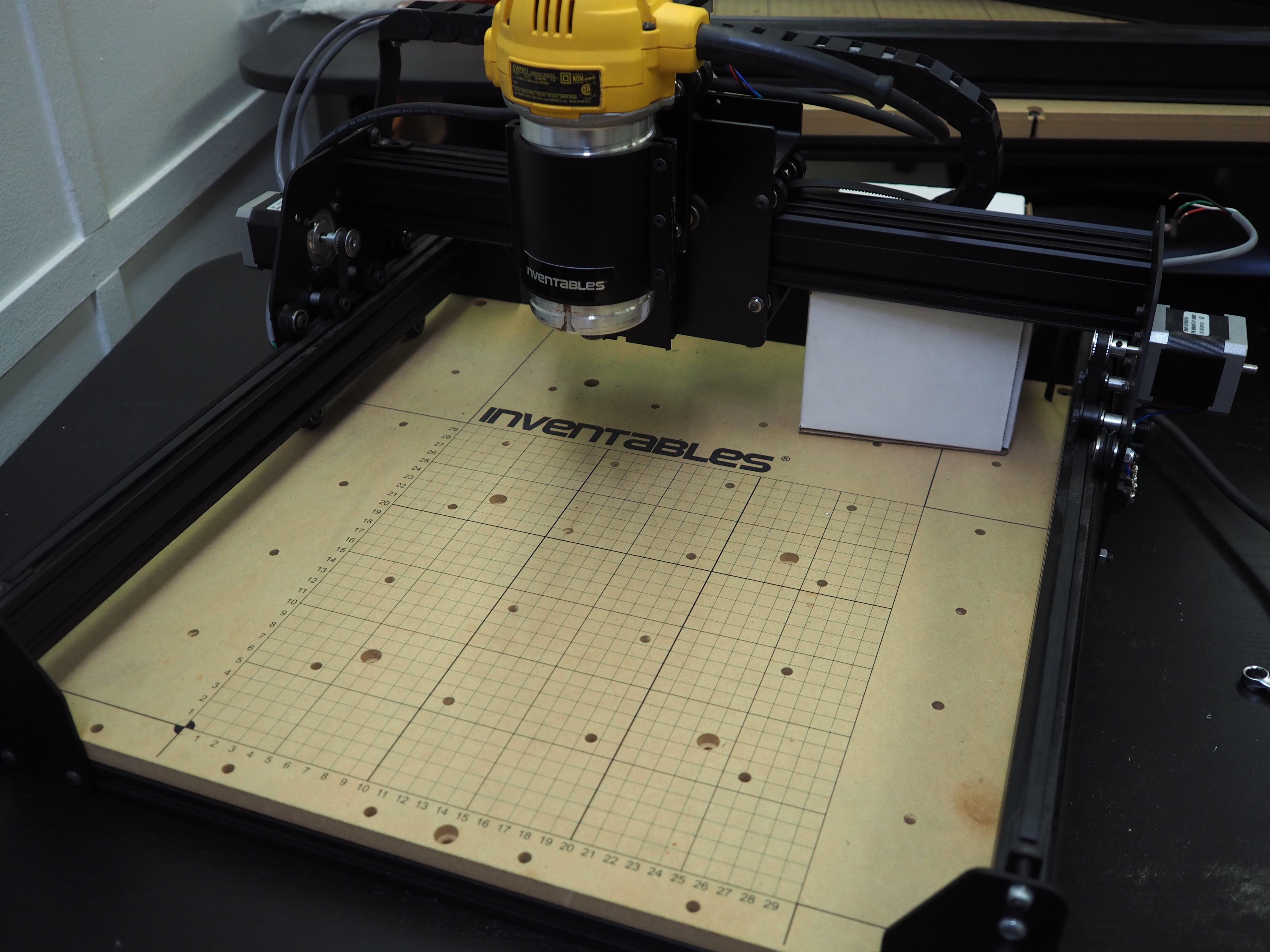
Position your gantry to the very back of the machine’s work area.
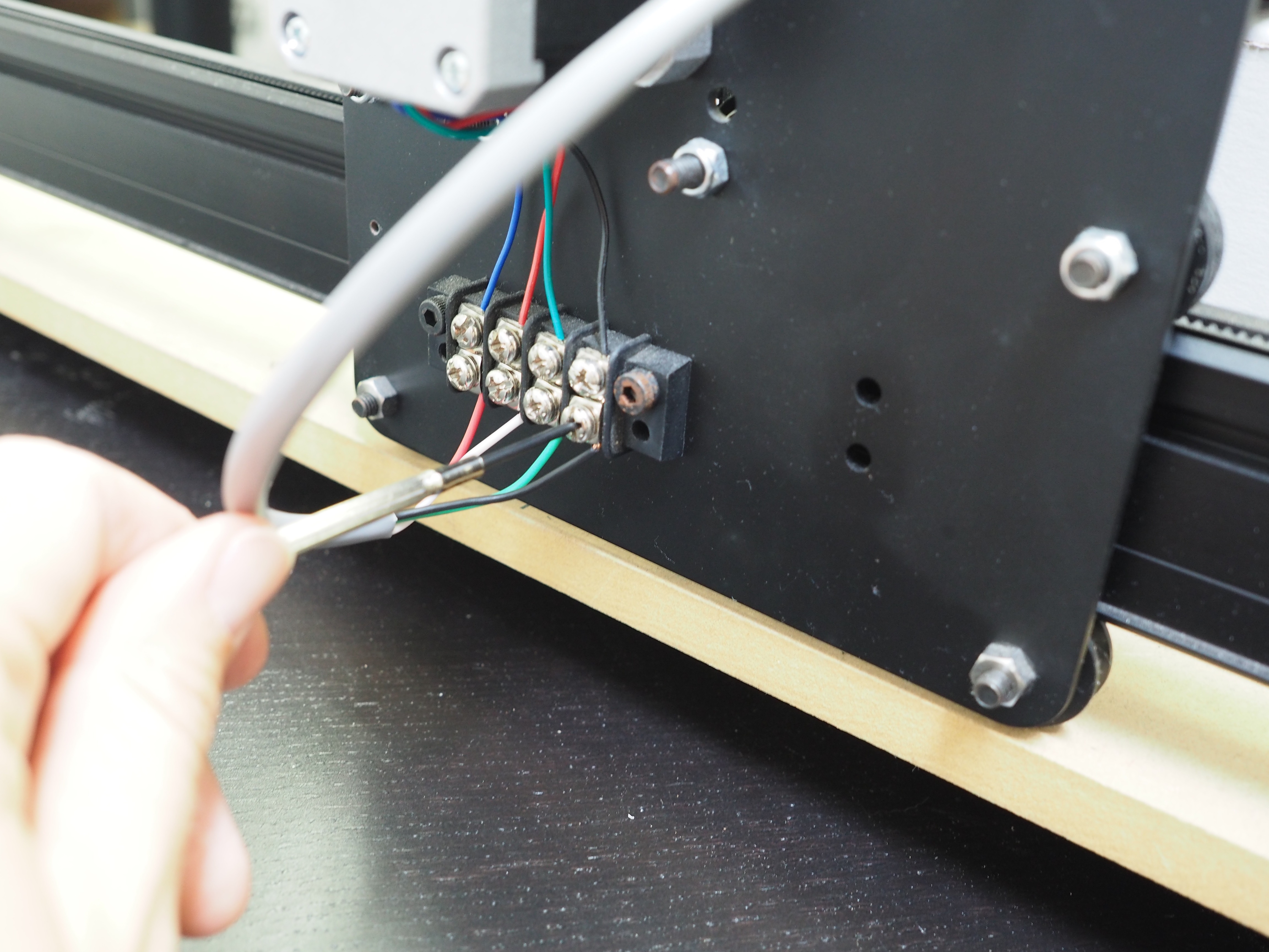
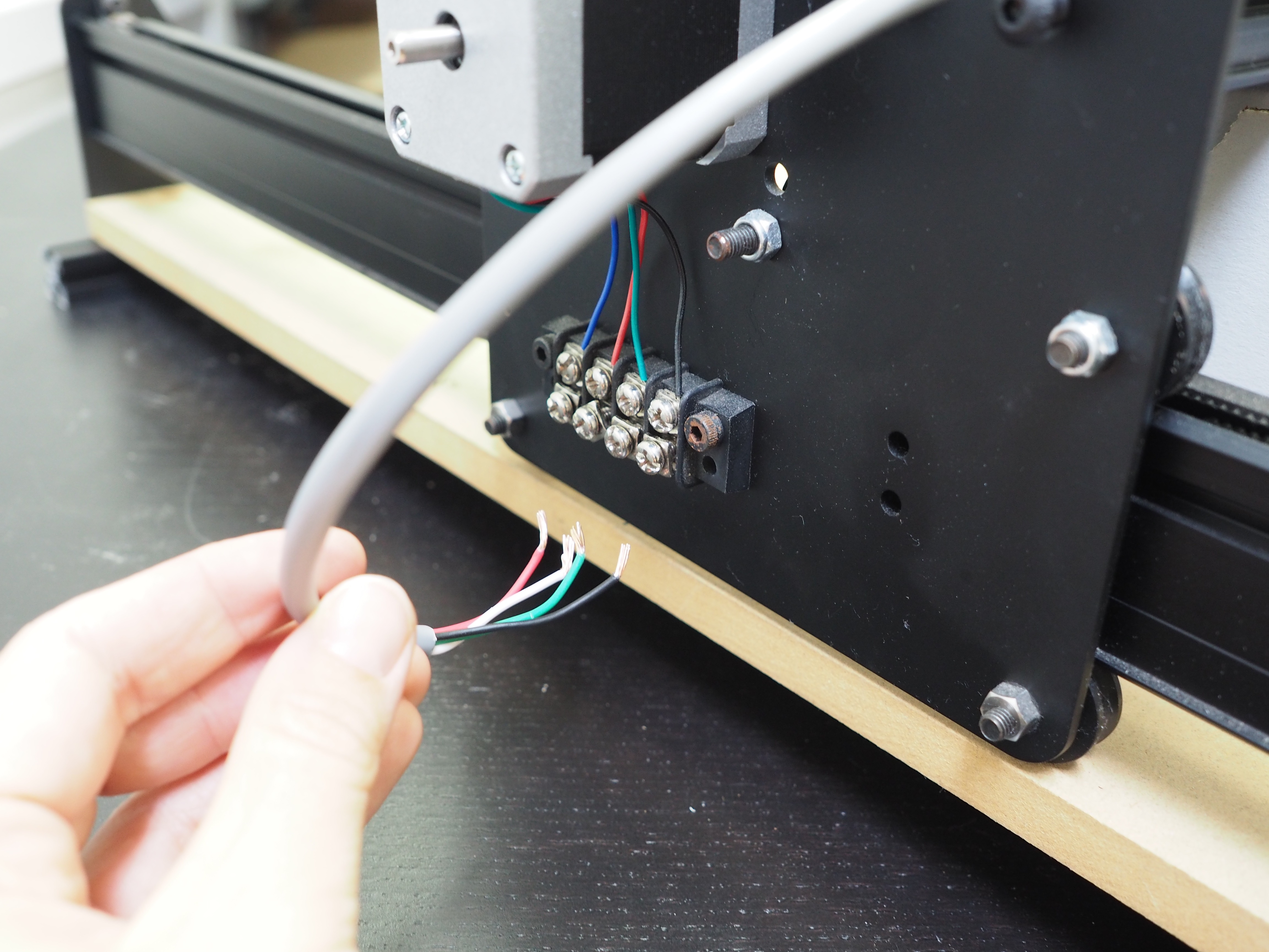
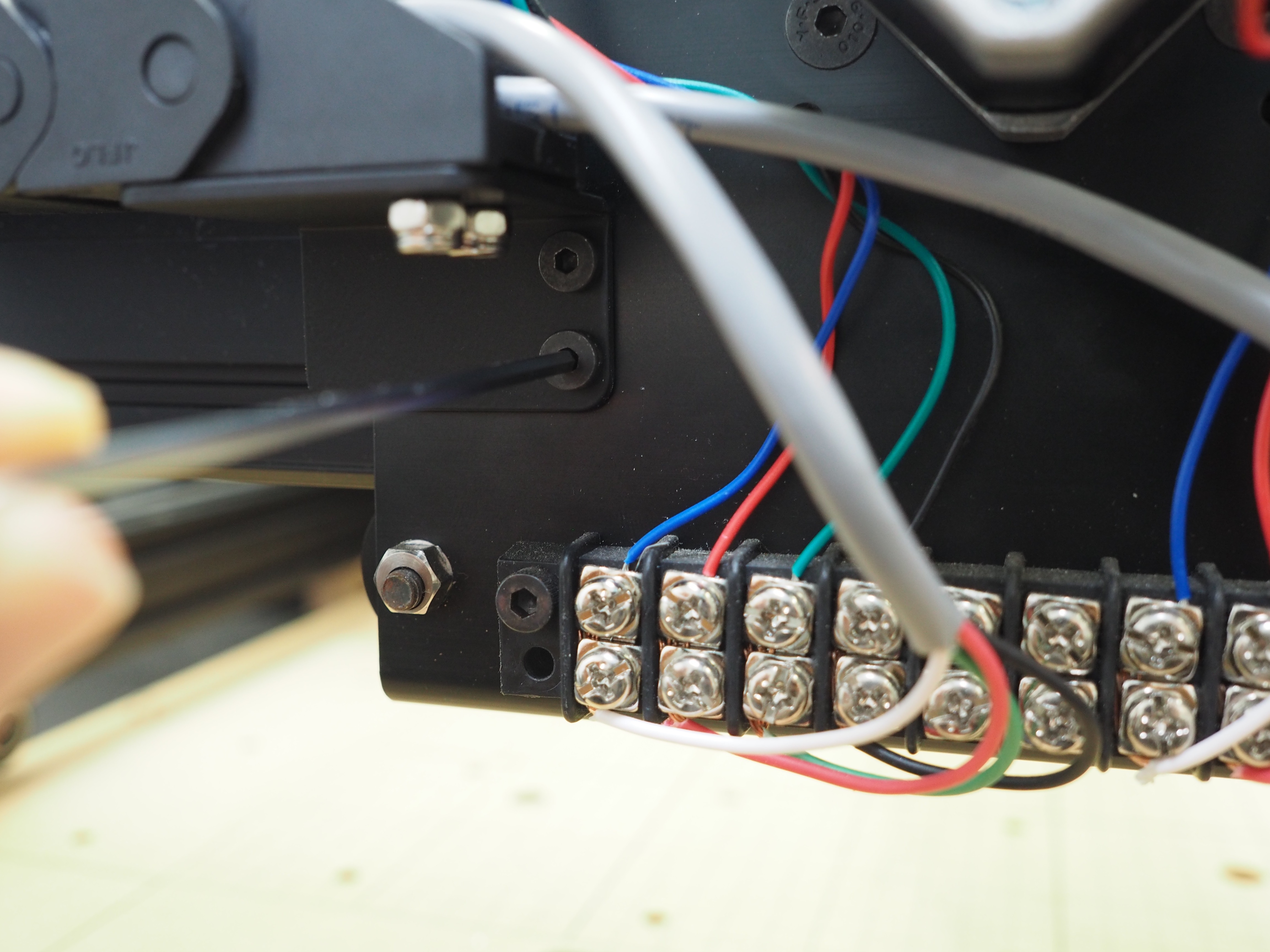
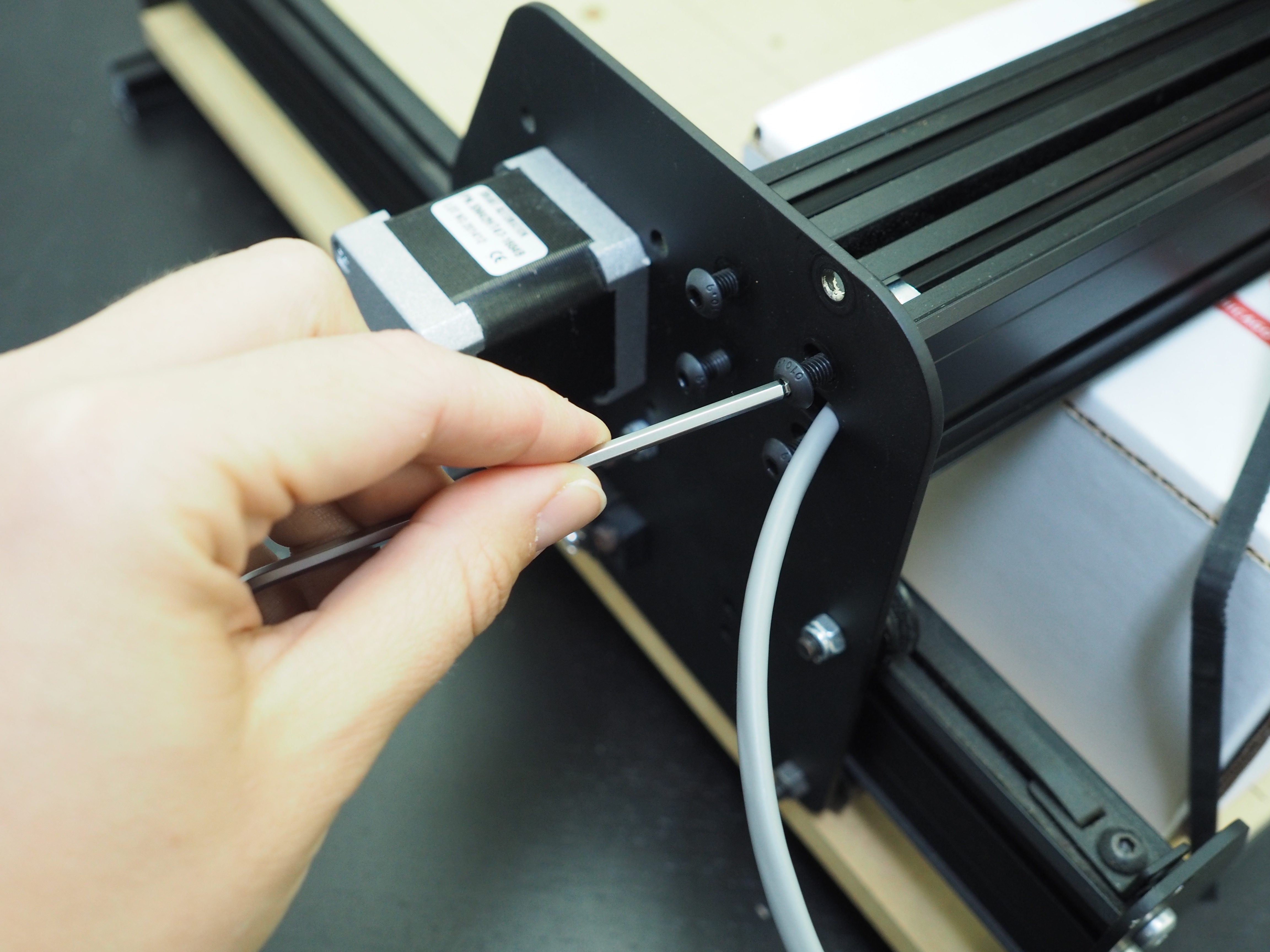
Begin by undoing the stepper motor wiring on the right side of the machine. This is the side of the machine that does not have the y-axis drag chain attached to it. You can undo the bottom terminal block wiring only and leave the stepper motor wiring in place. Undoing this stepper motor wire now prevents your wiring from being damaged during installation of the new rail.
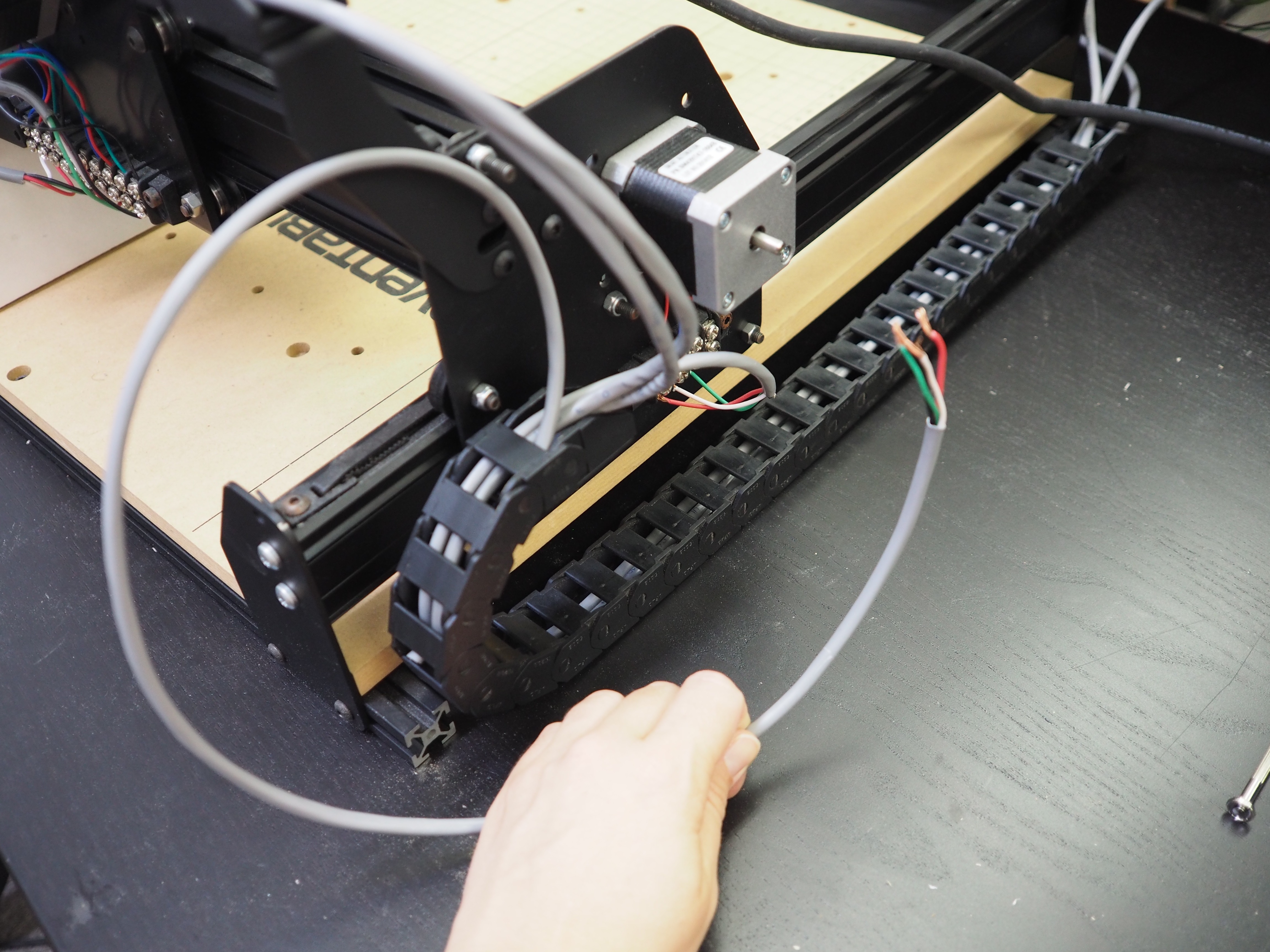
Once the stepper motor wire is removed, pull it through to the left side of the machine. The wire should no longer be through the gantry rail or right y-axis plate.
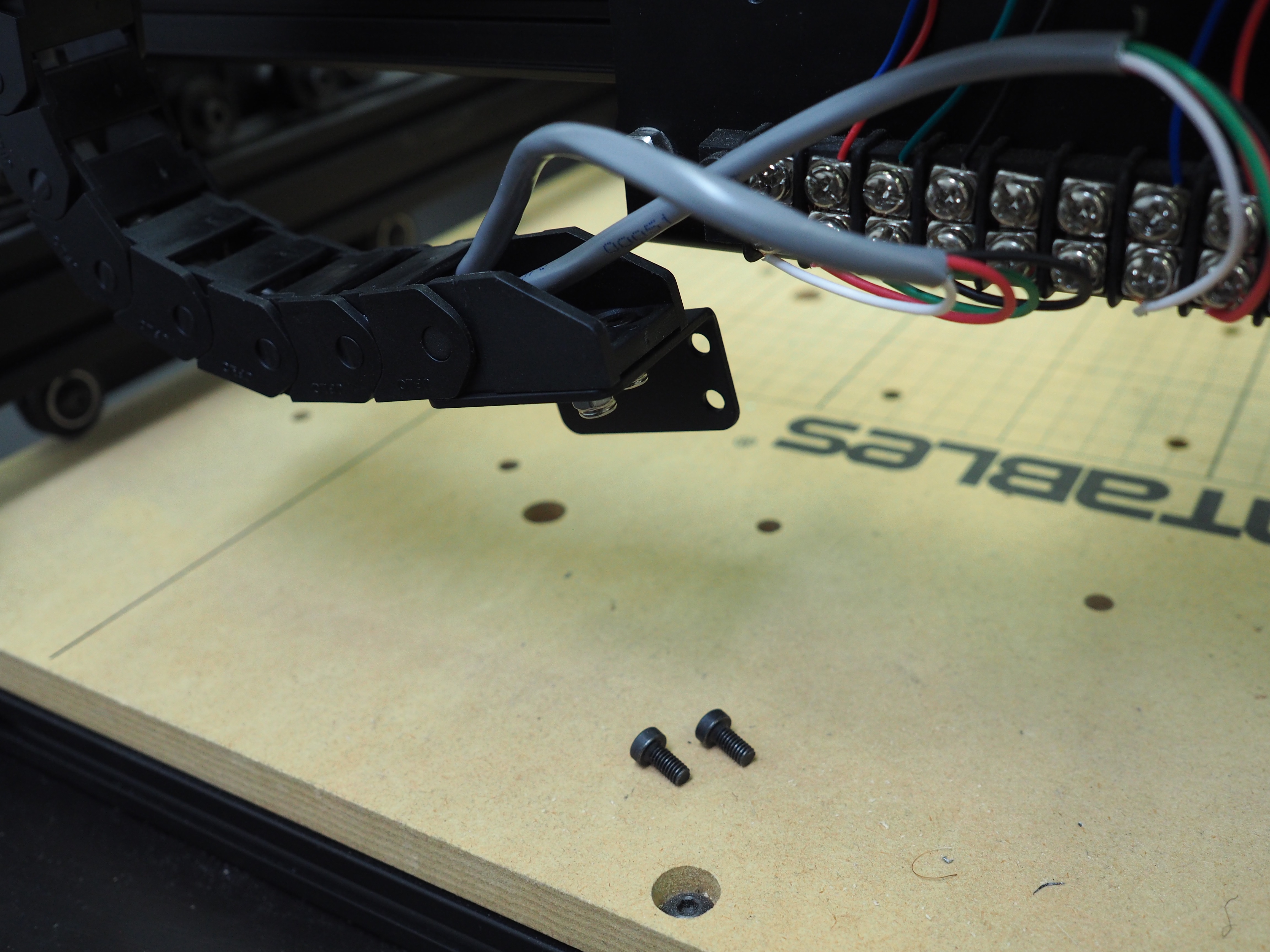
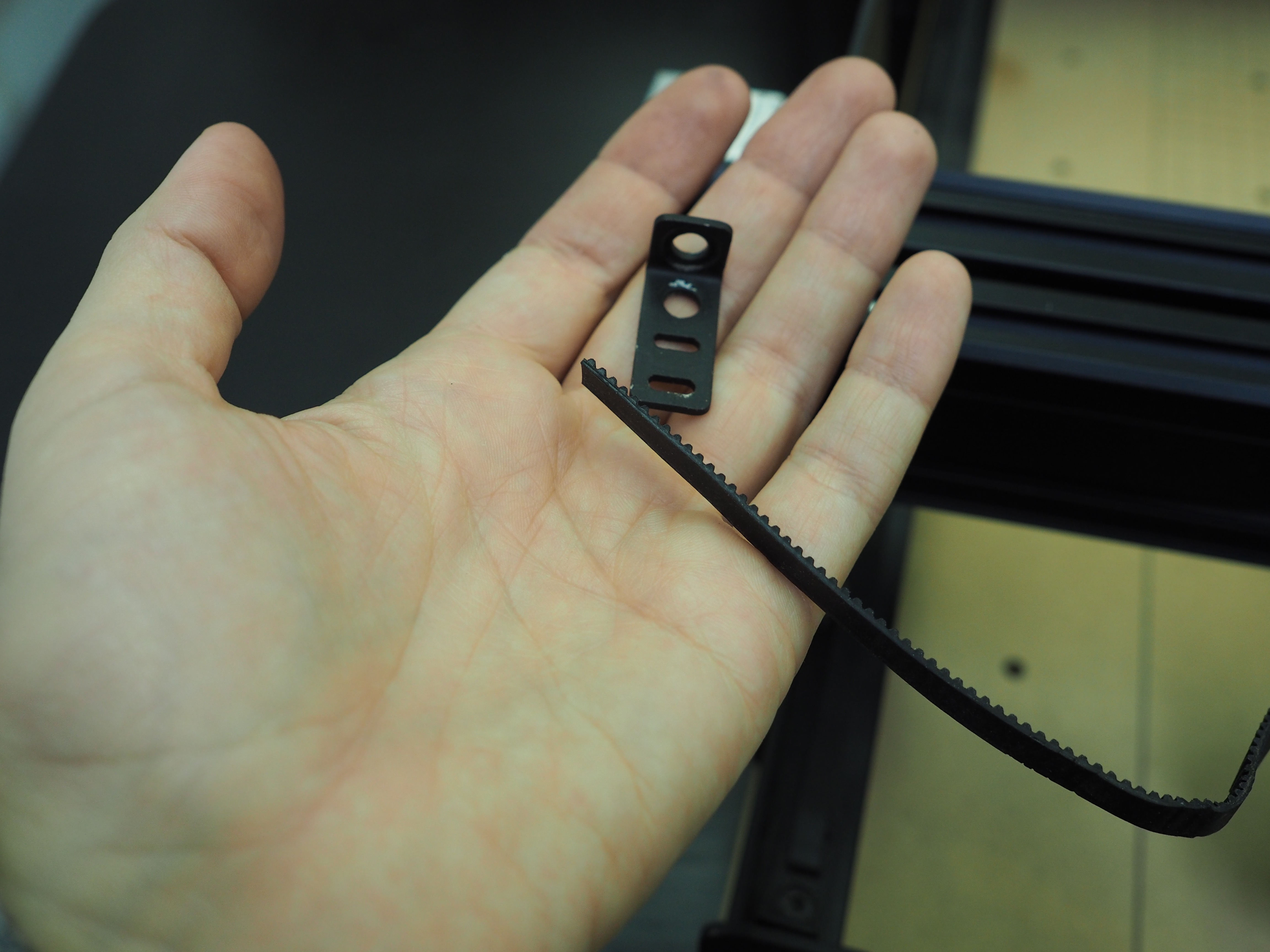
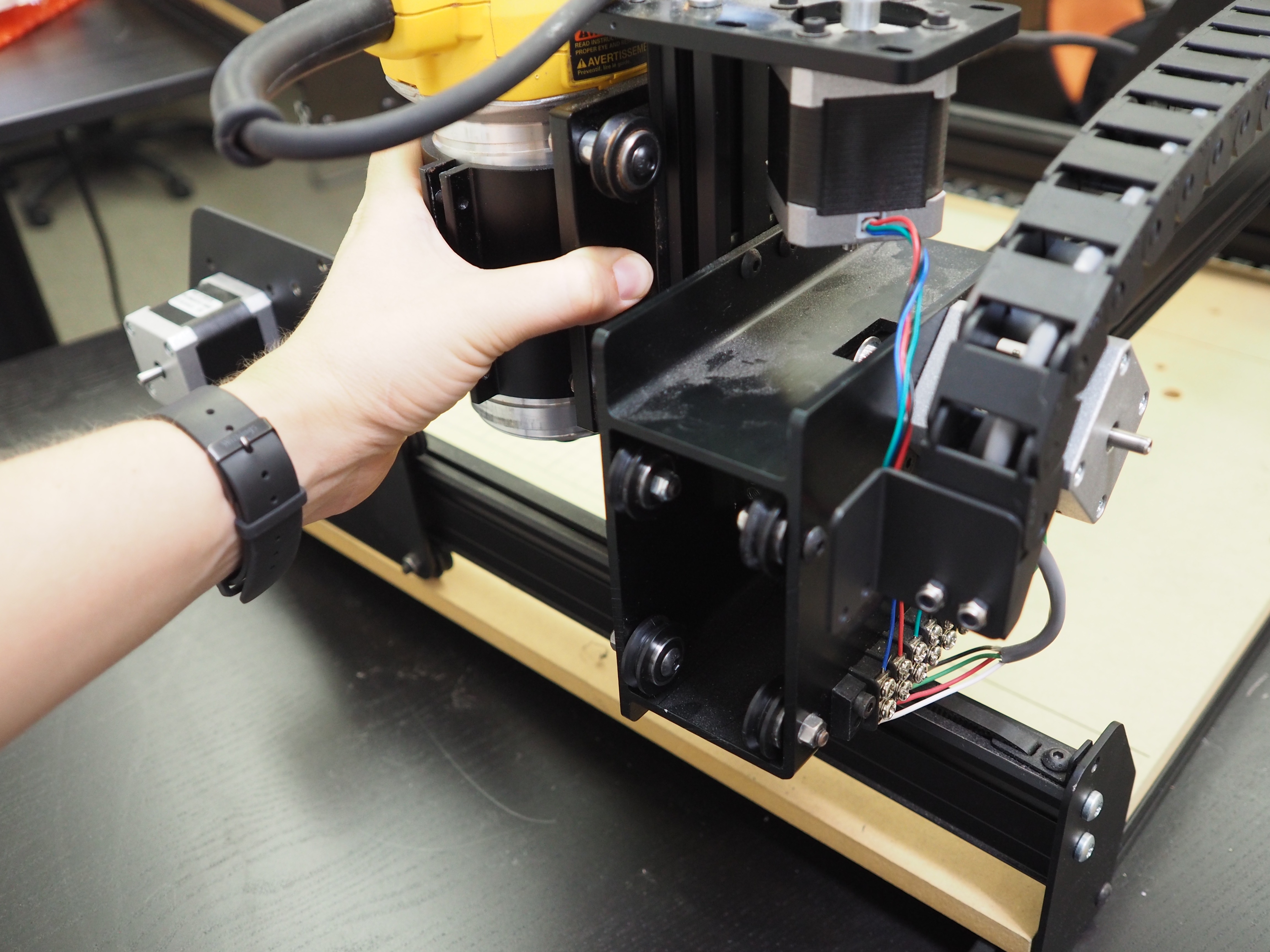
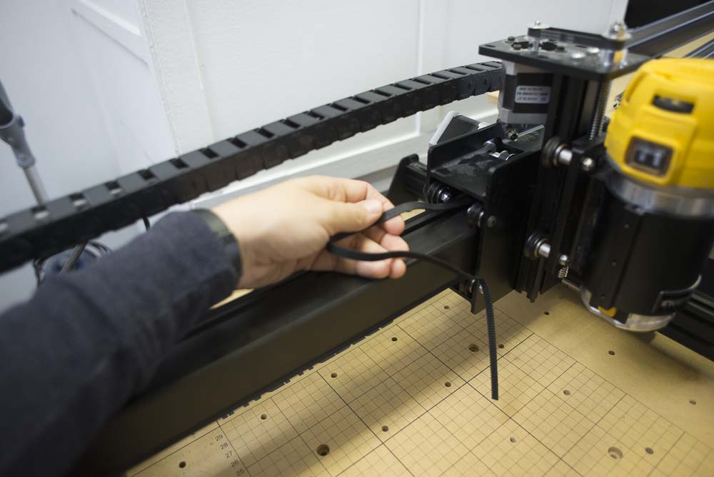
Next, remove your drag chain bracket from the x-carriage. You can leave the bracket attached to the bottom of the drag chain. Set aside these screws and save them for when we reassemble everything.
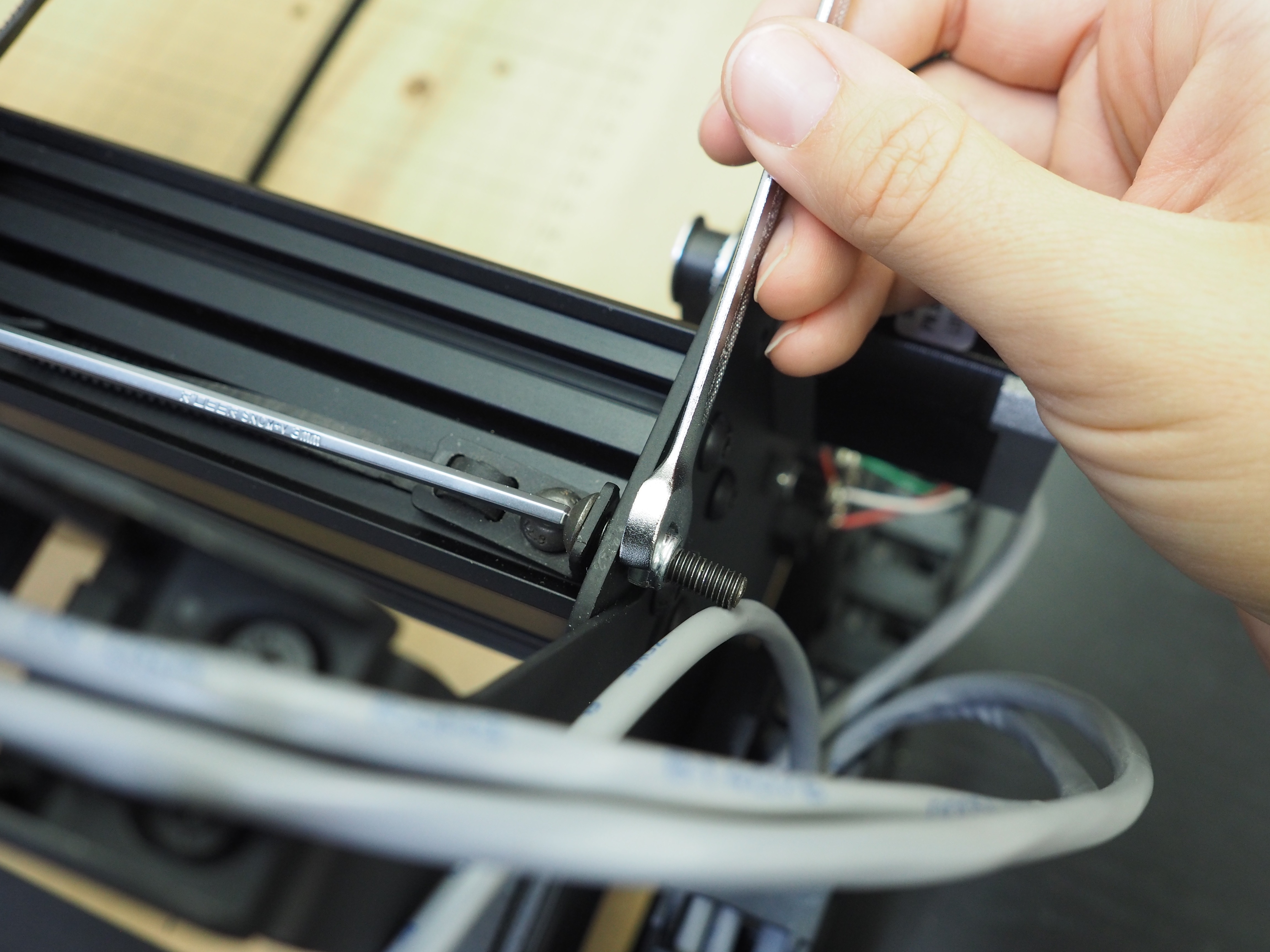
Once the drag chain bracket is removed, it’s time to undo the belting from the right side of the machine. This is the same side of the machine where we undid the wiring. Remove the belt clip and screws from the belt; set them aside for later.
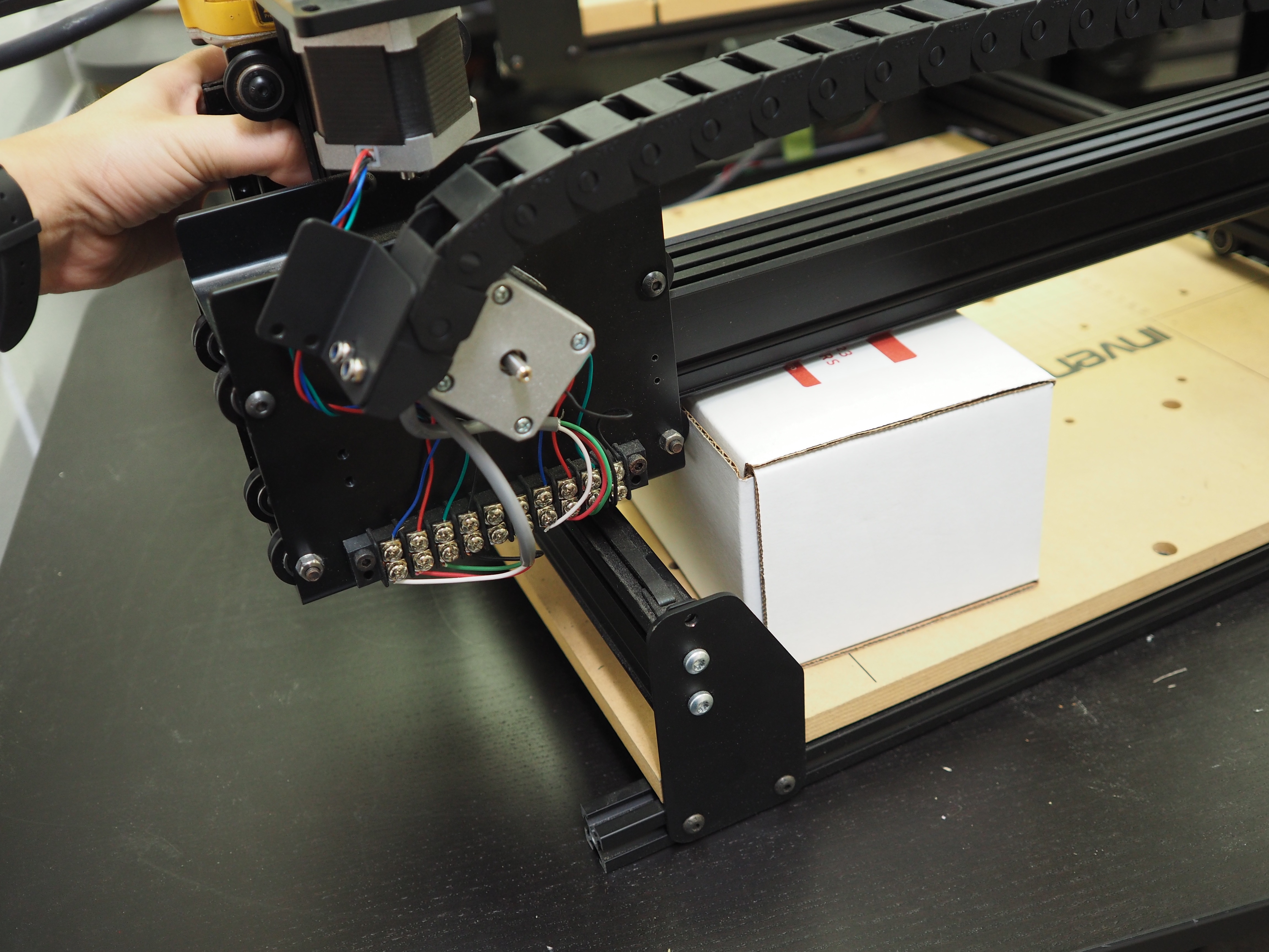
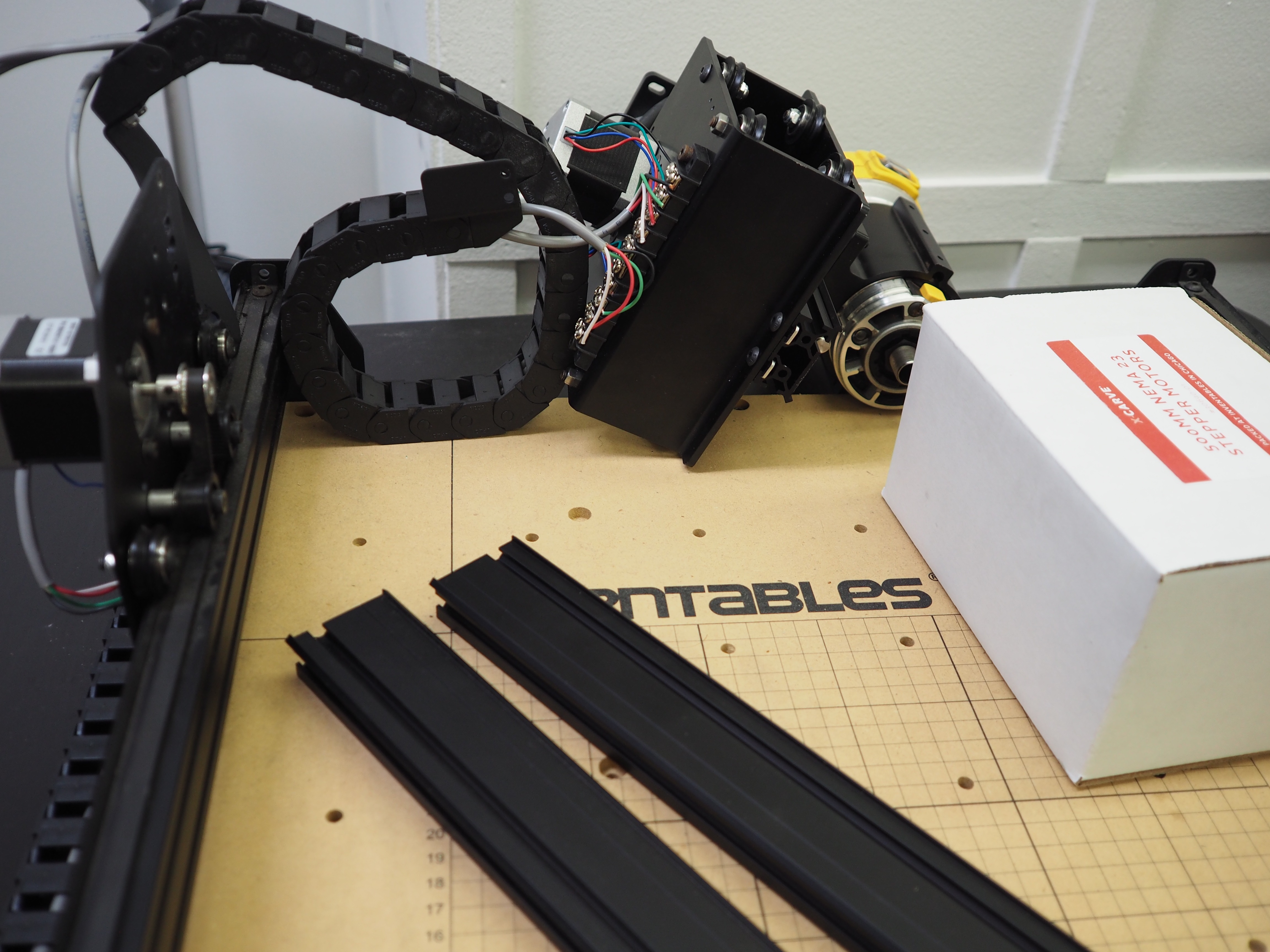
Before advancing, find a way to prop up the MakerSlide rail on the right side of the machine. If you have a 1000mm machine, we suggest having someone else help with this part of your installation. We used an old NEMA 23 stepper motor module box to support our gantry and spindle, but feel free to use anything that will keep the rail level when we start disassembling the gantry.
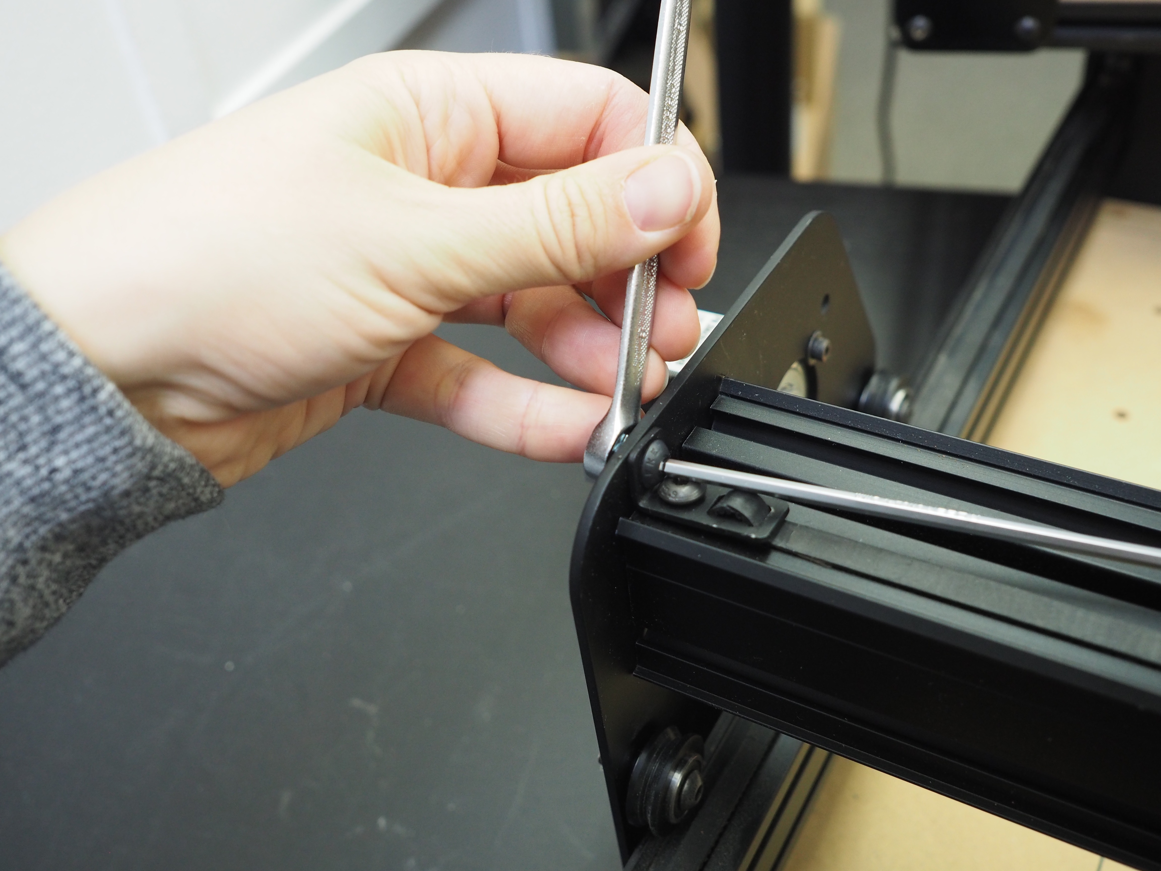
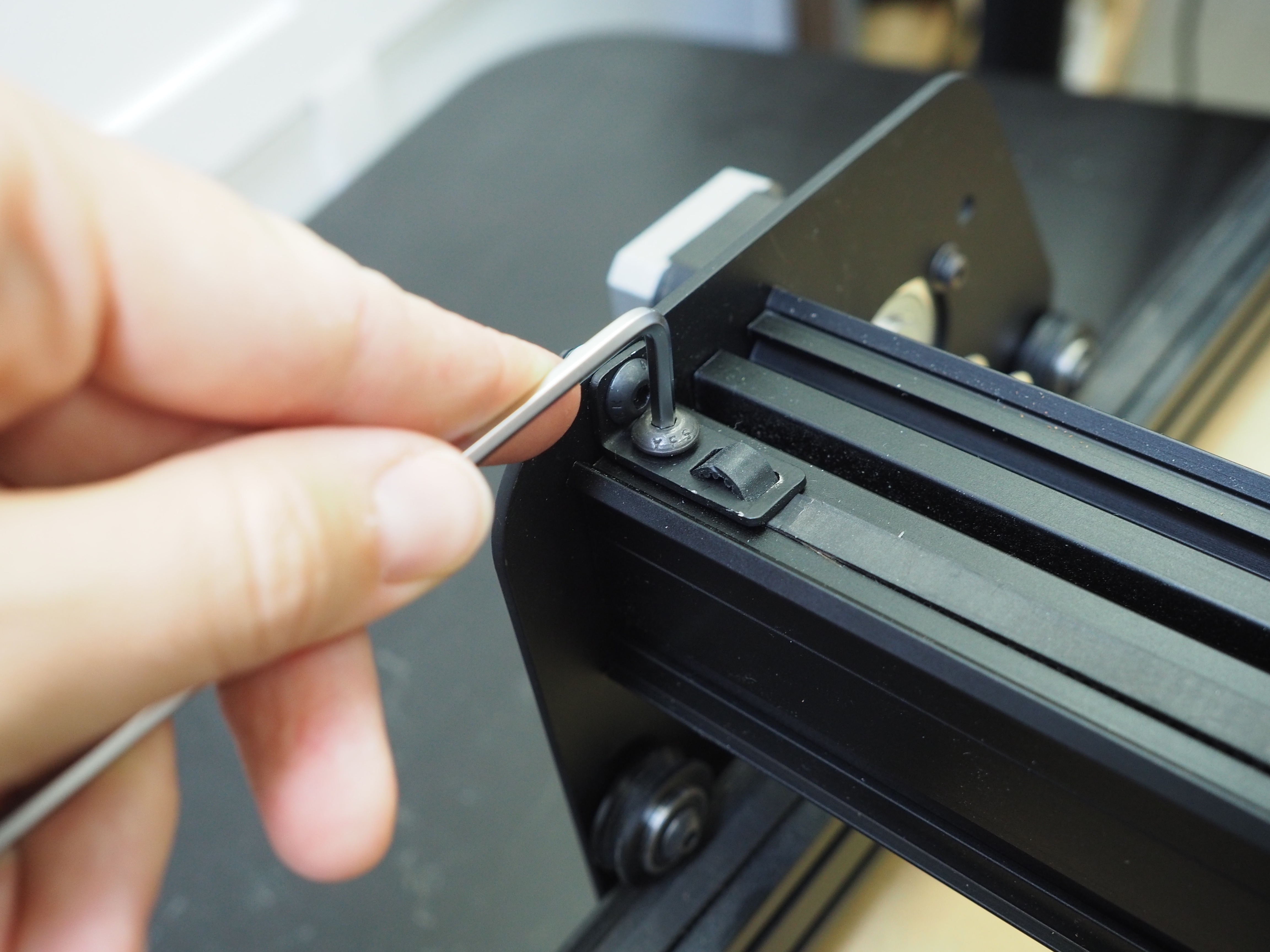
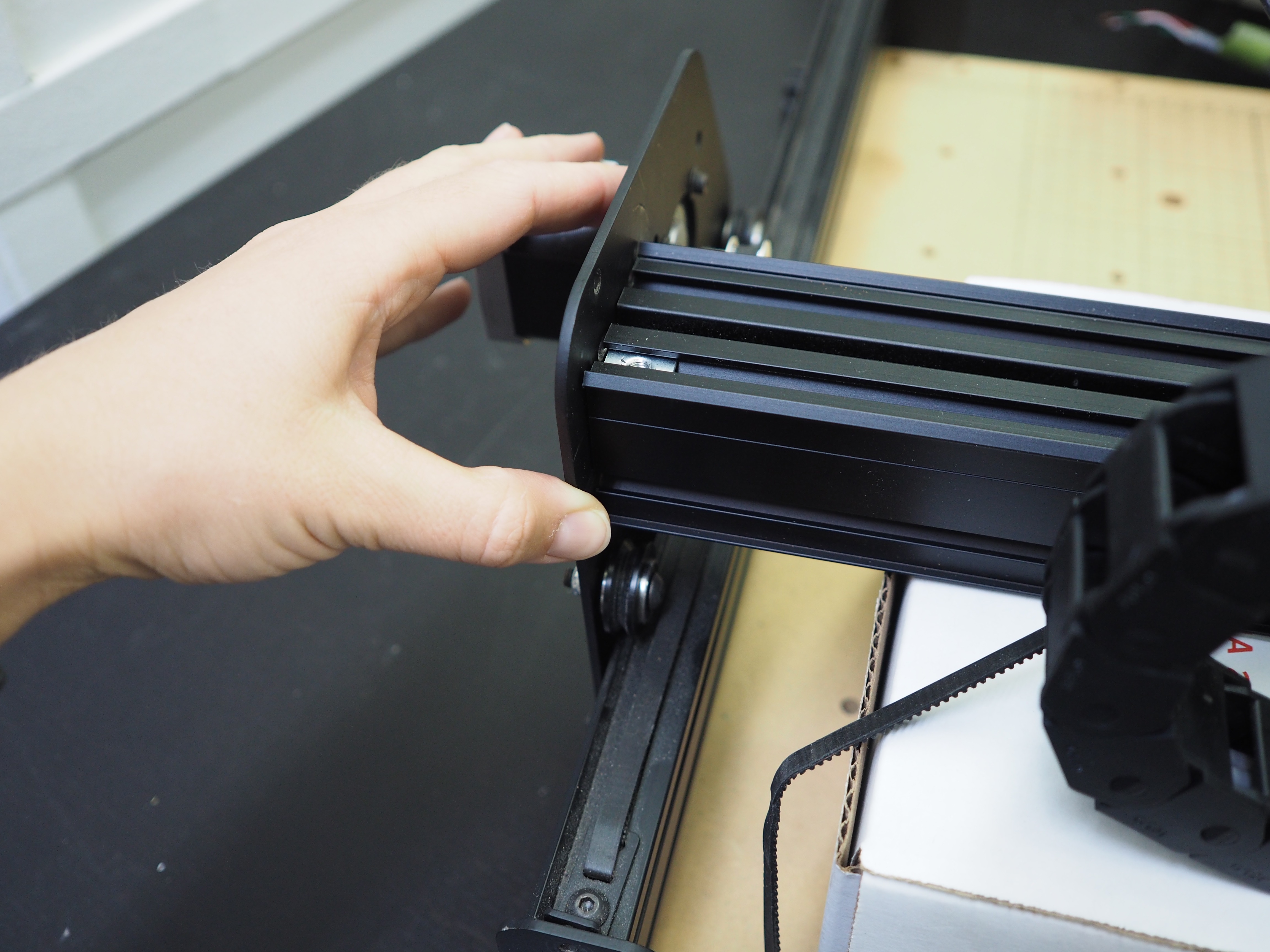
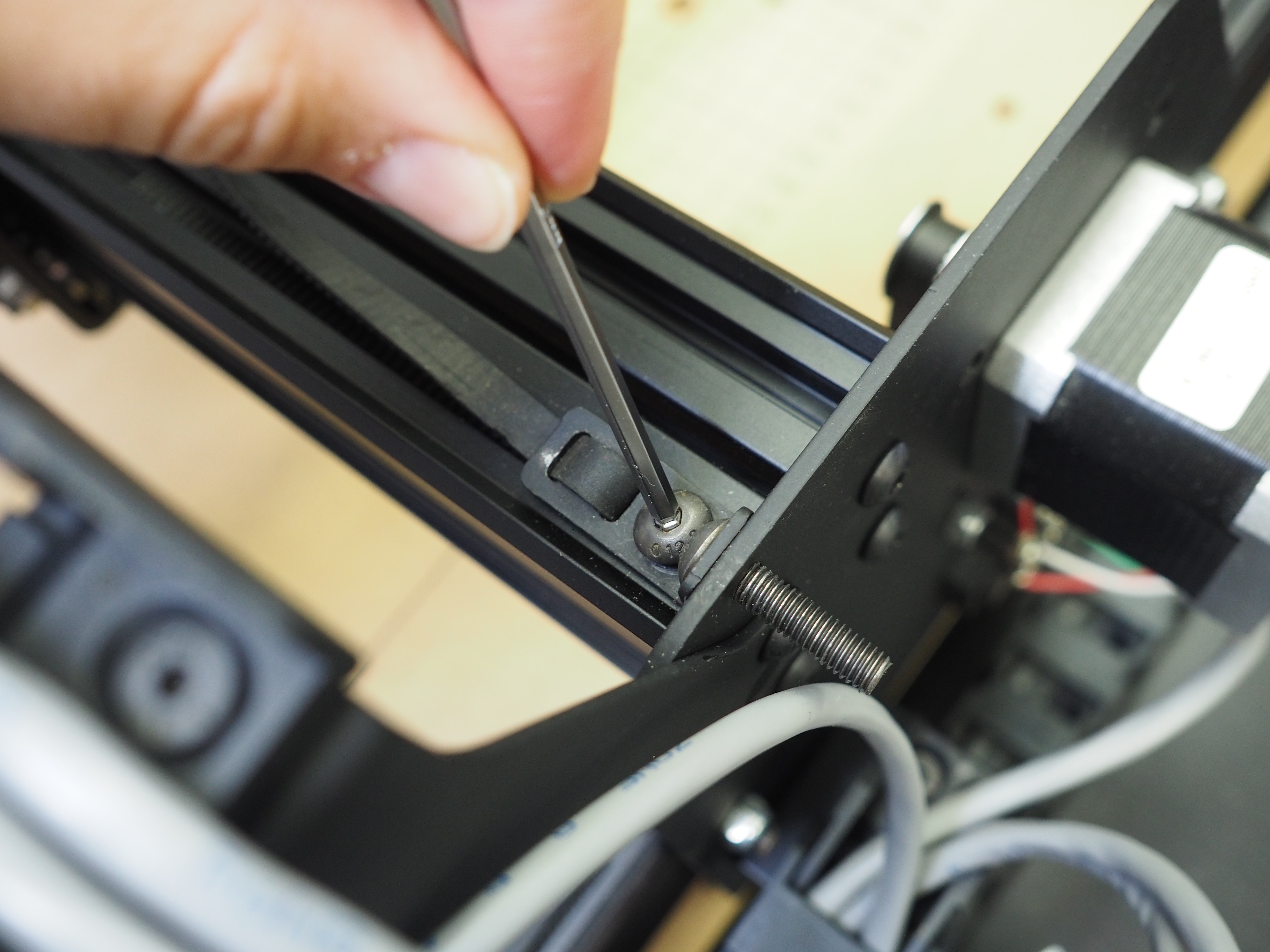
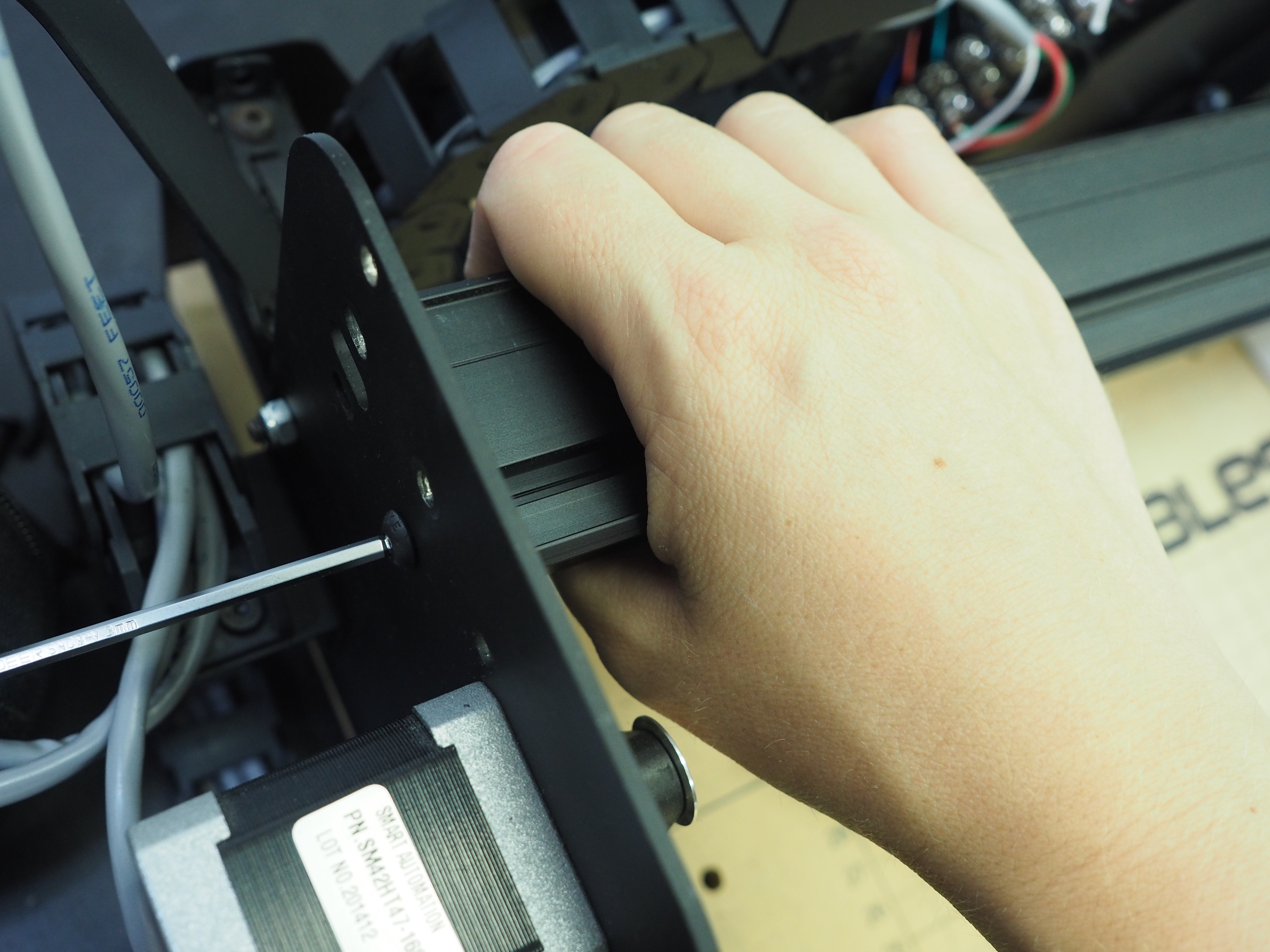
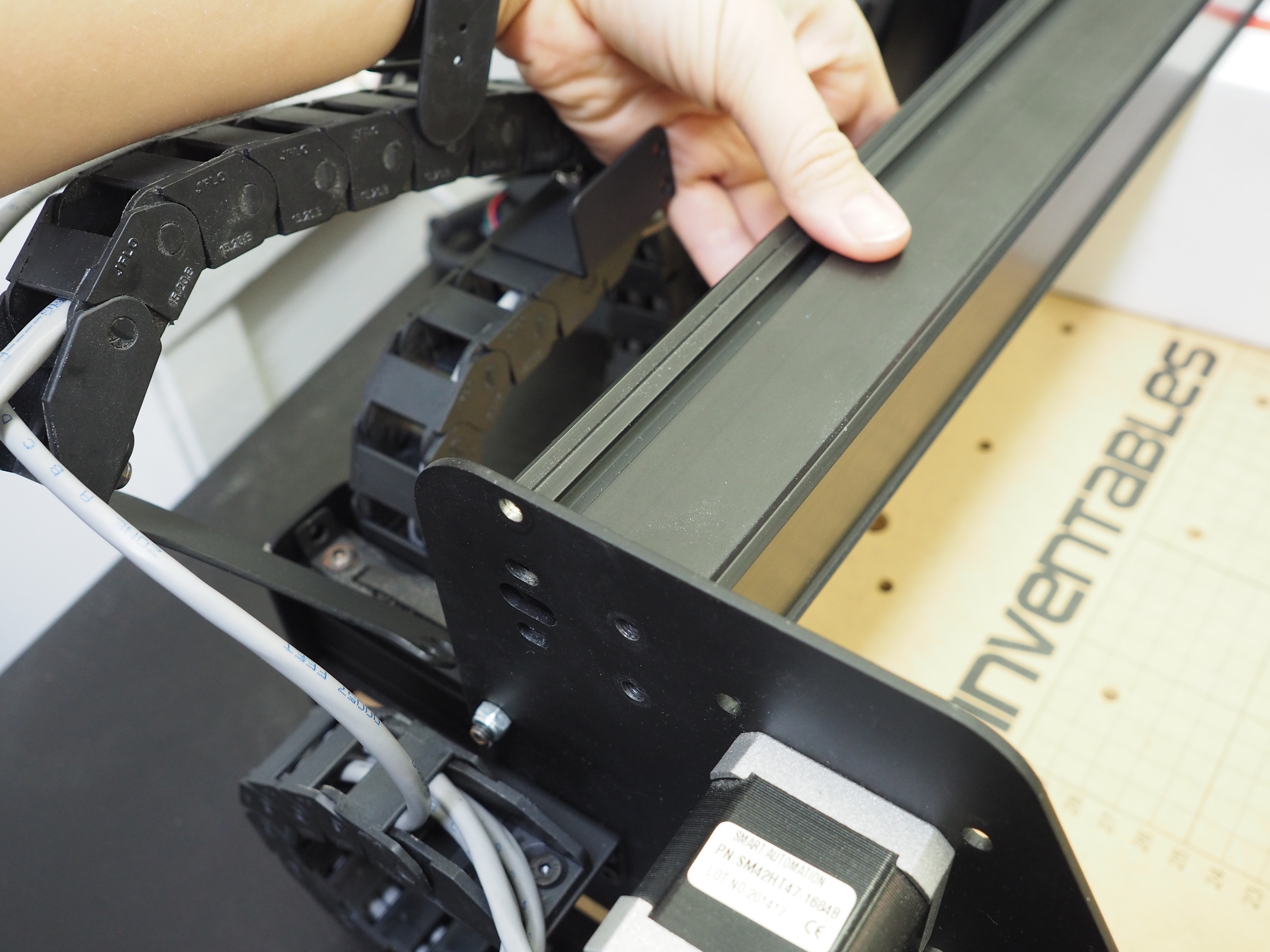
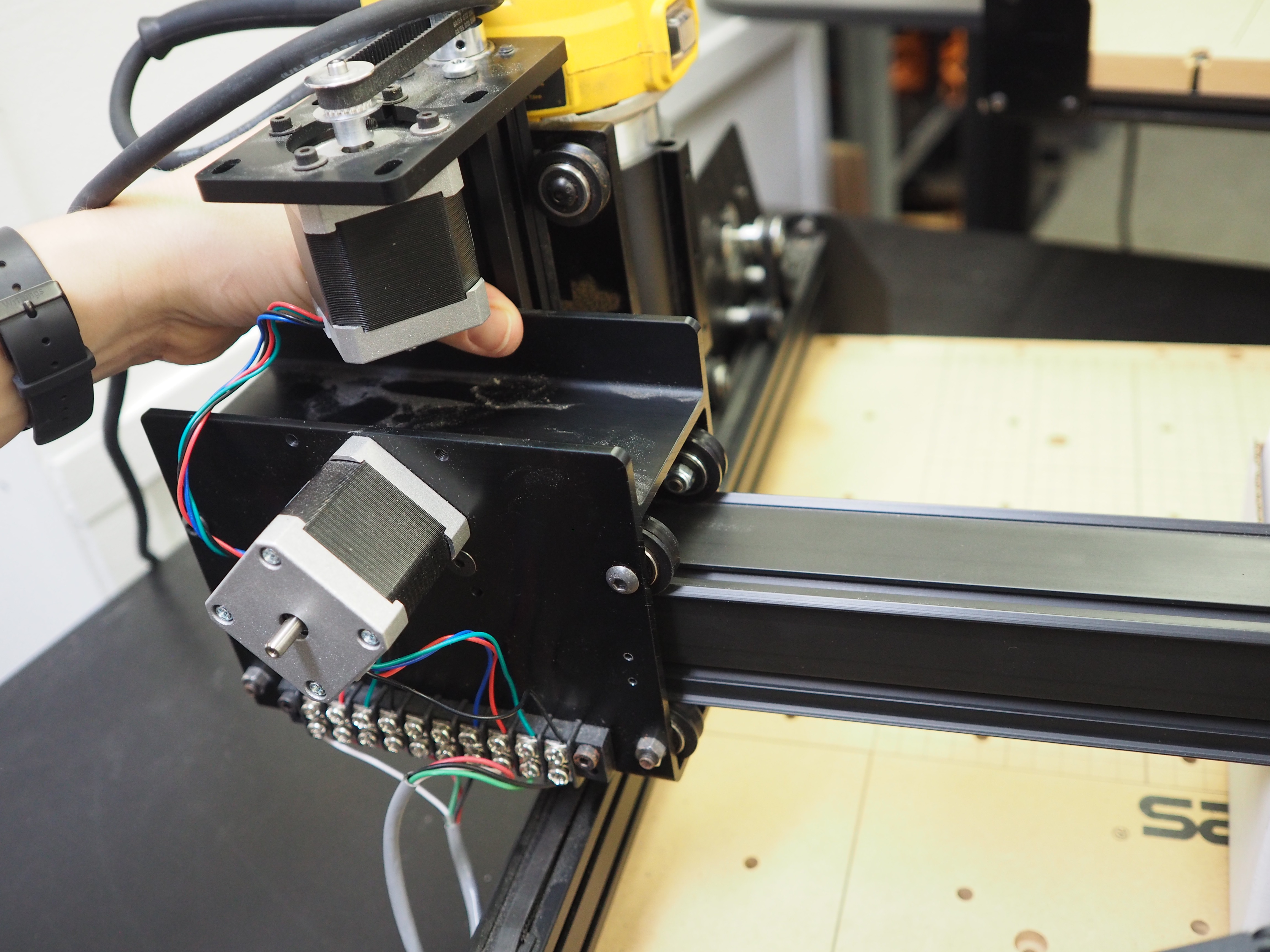
Once your rail is fully supported, start removing the four button head cap screws securing the gantry rails to the right y-axis plate. Set these aside for later. Your rail should safely rest on the box you put into place.
You should now be able to safely slide the right y-axis plate towards the front the machine. You may need to wiggle the rails slightly to get the plate fully moved away from the rails. Push the y-axis plate all the way to the front of the machine so you have space to remove the x-carriage.
Undo the screws holding the belt clip in place on the left side of the machine. The belt should now be detached from both y-axis plates, but still threaded properly over the pulley on the x-carriage. This way, when you replace the x-carriage back on the new rail, you don’t need to re-thread the belting back over the pulley.
If possible, use two people for this next part.
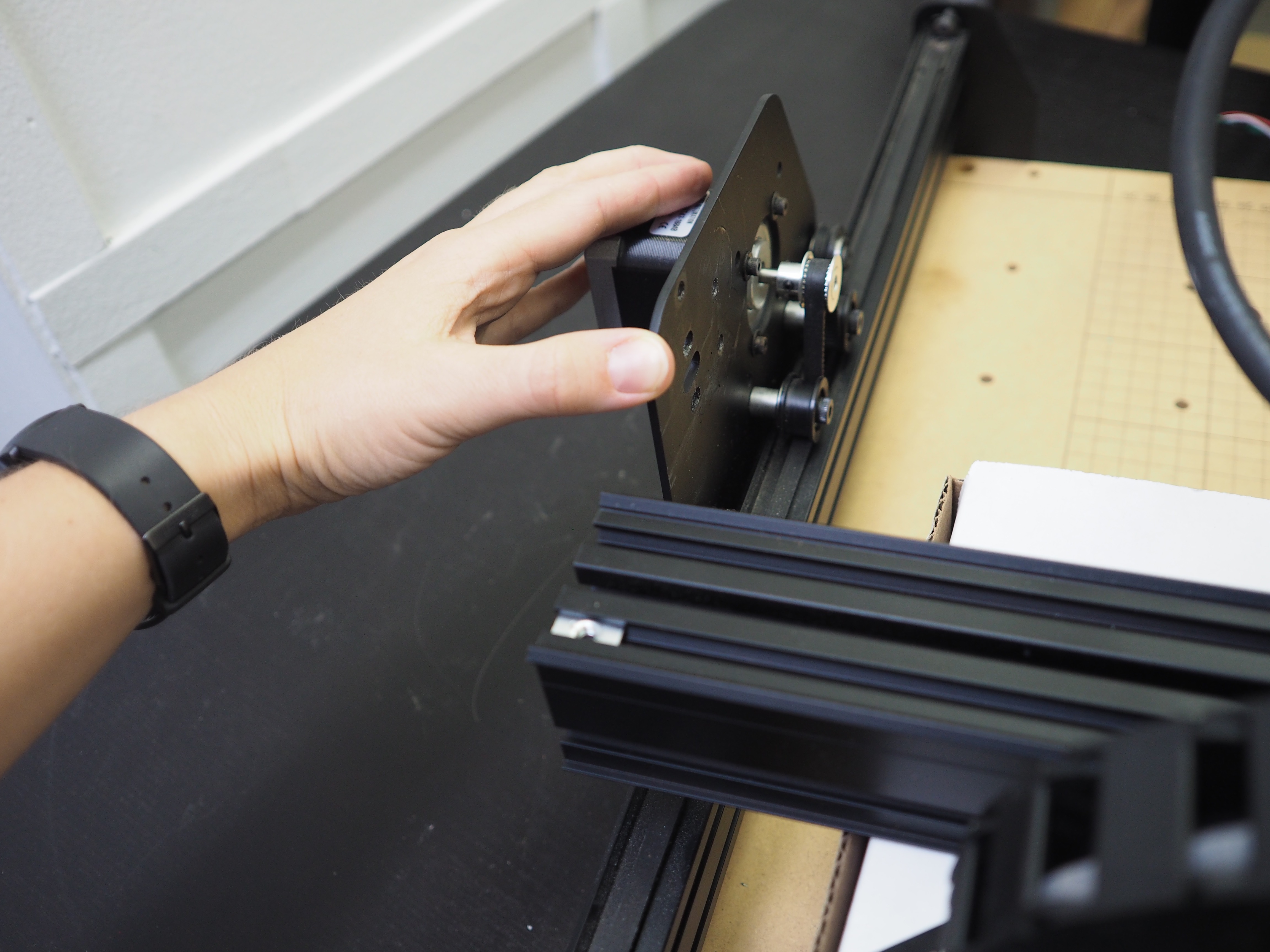
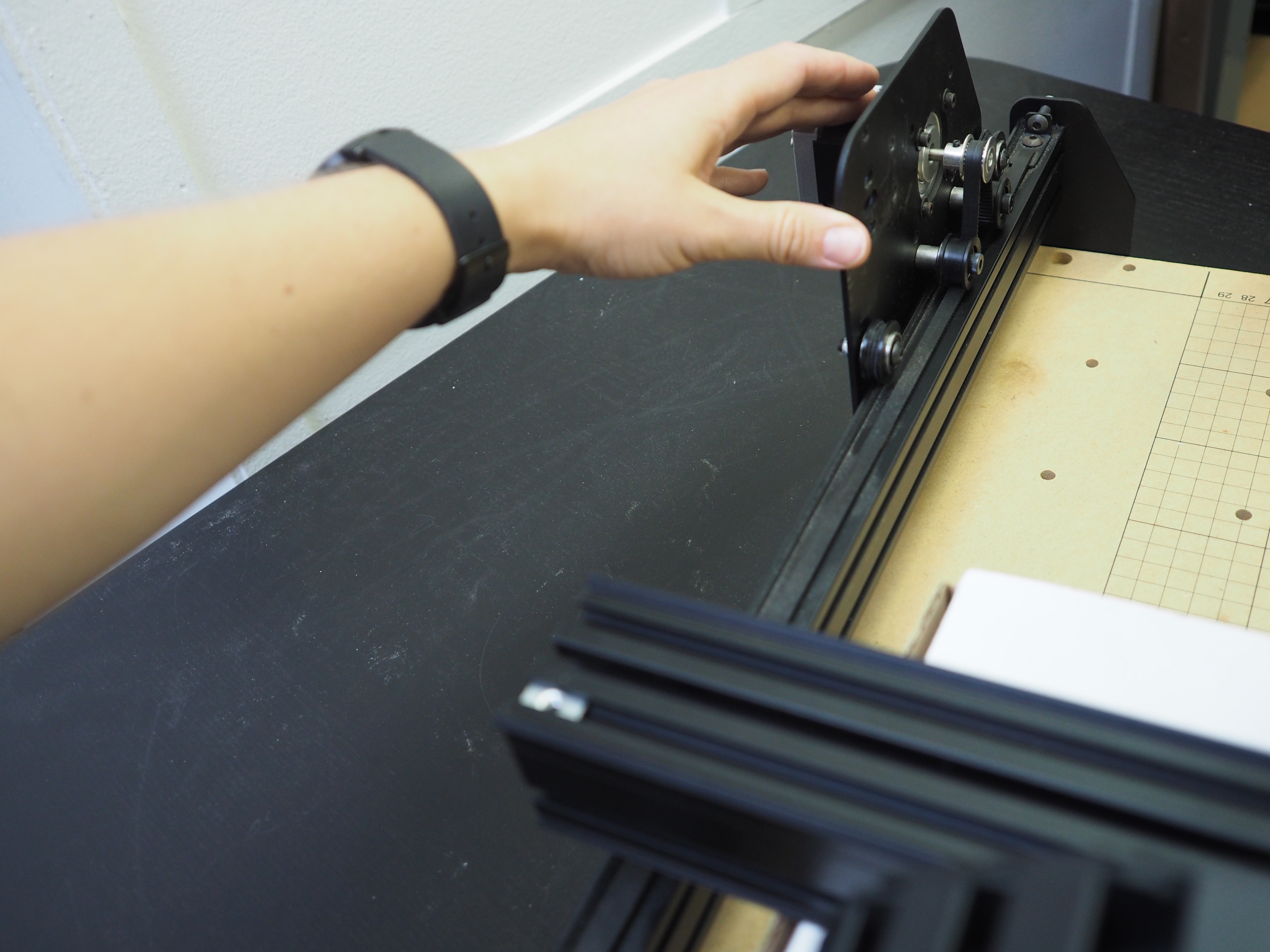
Slide the x-carriage all the way to the right side of the machine. Reposition your box to the other side of the x-carriage, so when you remove the x-carriage completely the rails will still be supported by the box.
When you’re ready to slide the x-carriage all the way off the gantry, make sure you clear the y-axis rails and don’t damage the wiring on the back of the x-carriage gantry. Try to keep the belting from being damaged inside the x-carriage as you slide the carriage off the rails. Make sure the belting stays draped over the pulley once the carriage is off the rails.
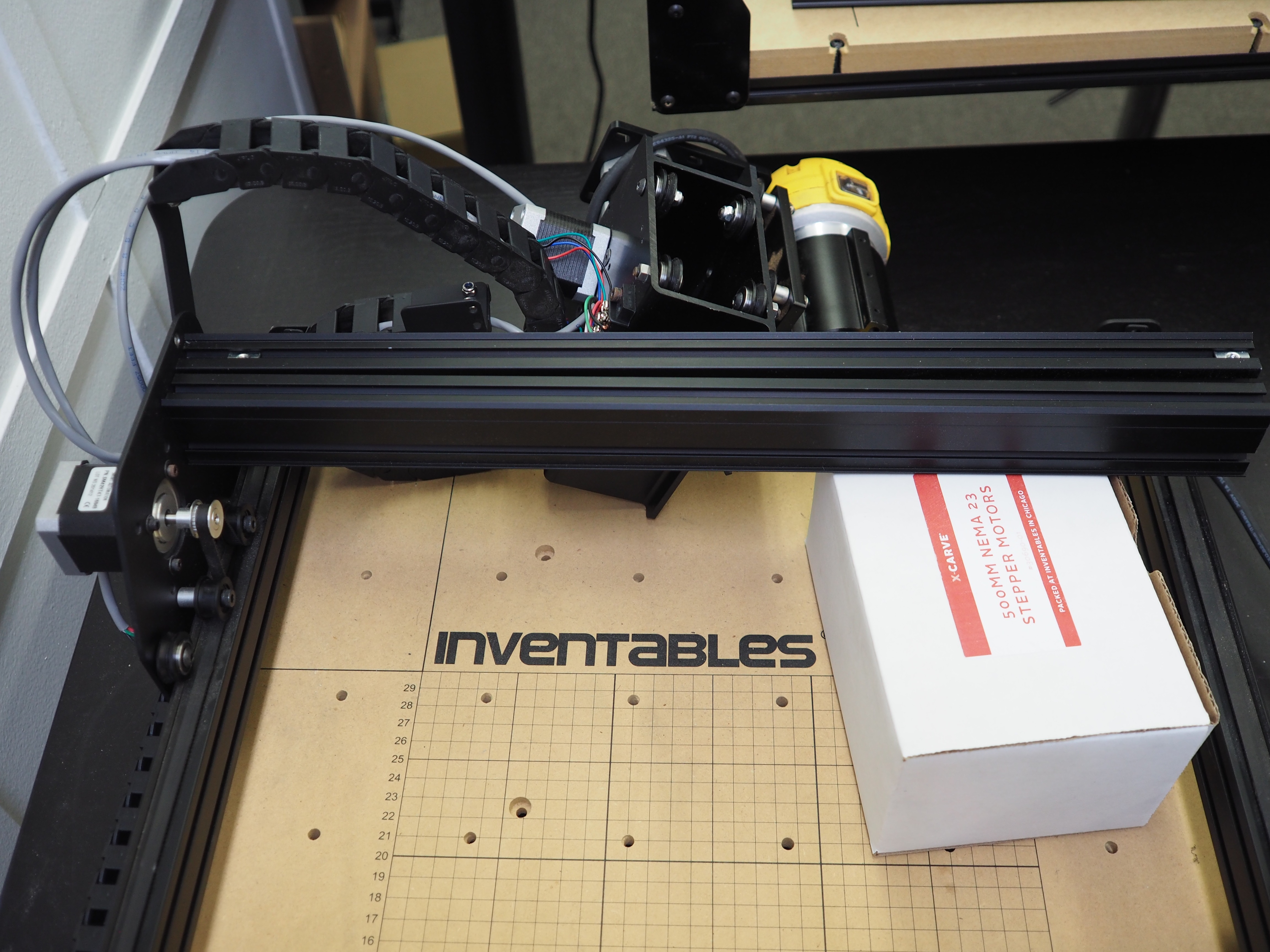
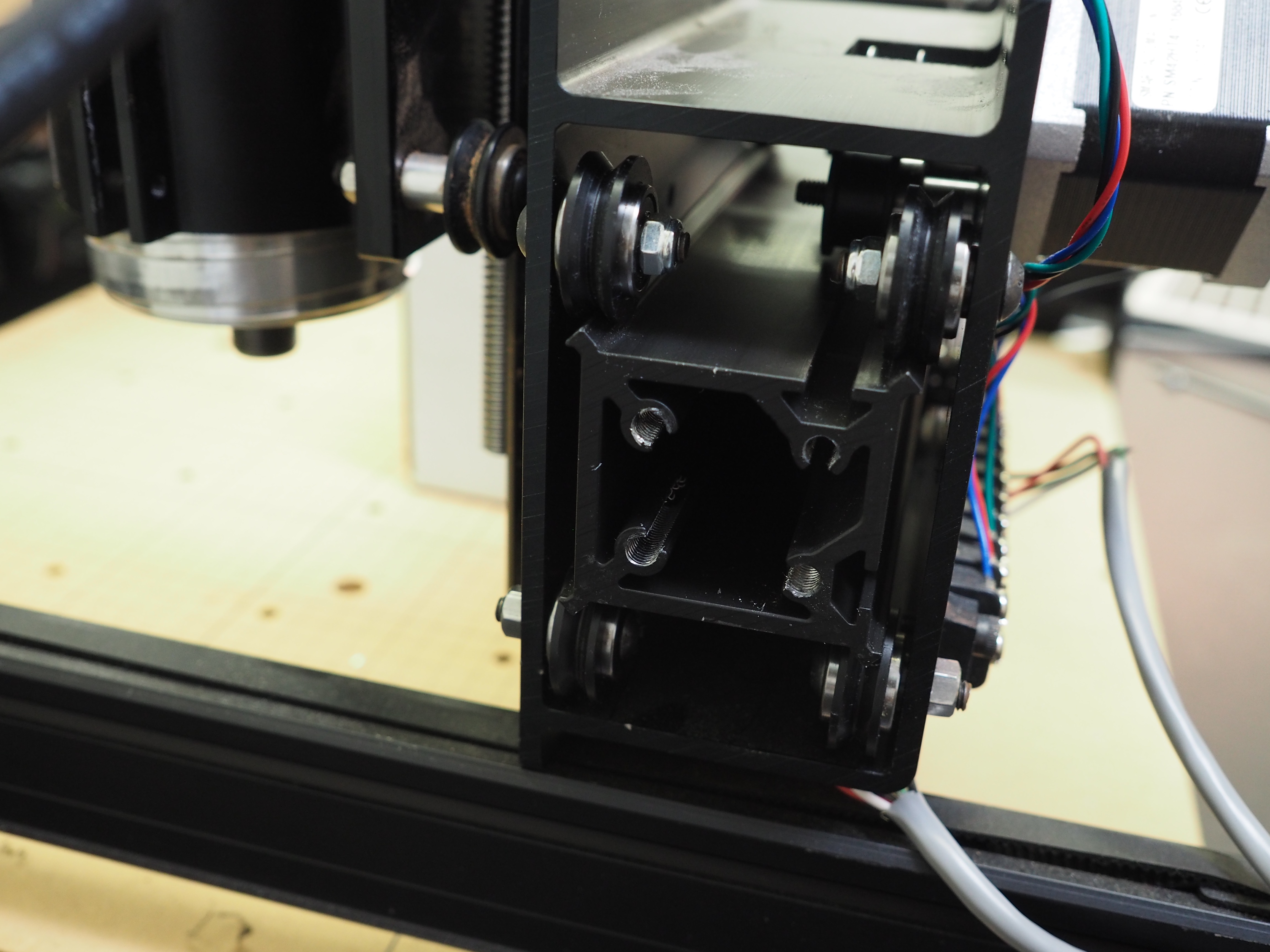
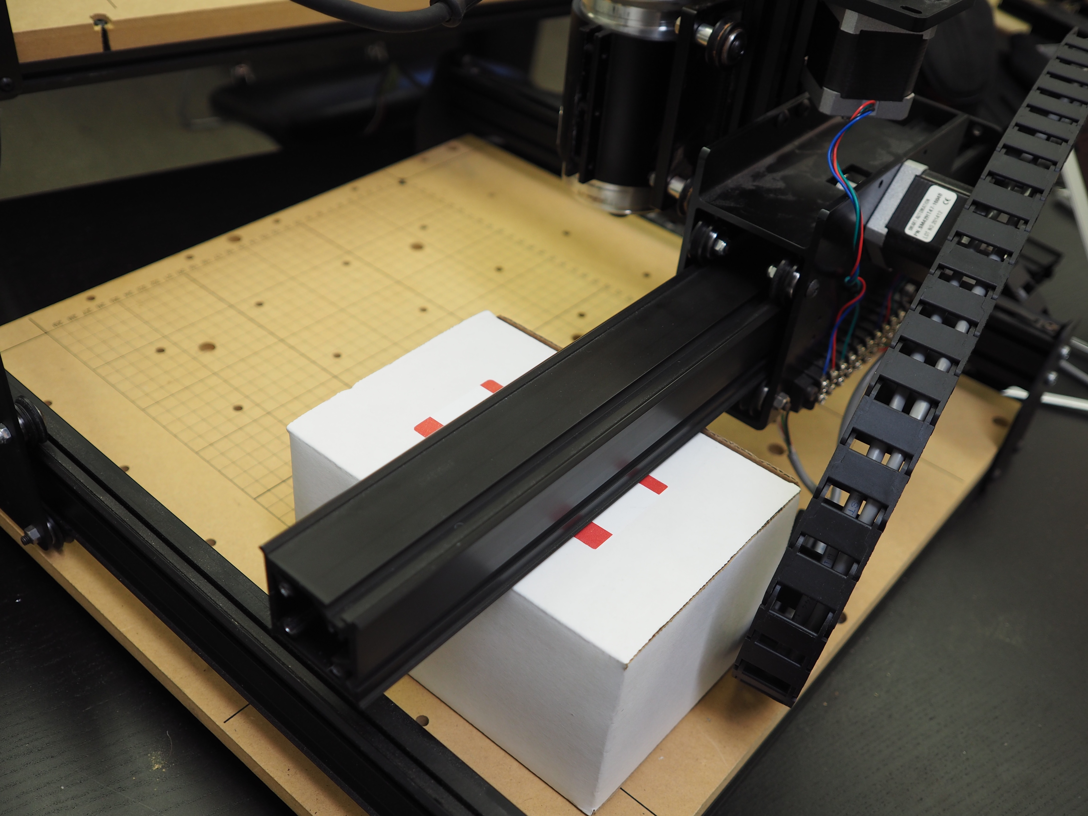
When you are finished, your machine should have the x-carriage and belting removed. The gantry should only be held in place on the left side of the machine and the box on the right side of the machine. From the front of your machine, it should look like this:
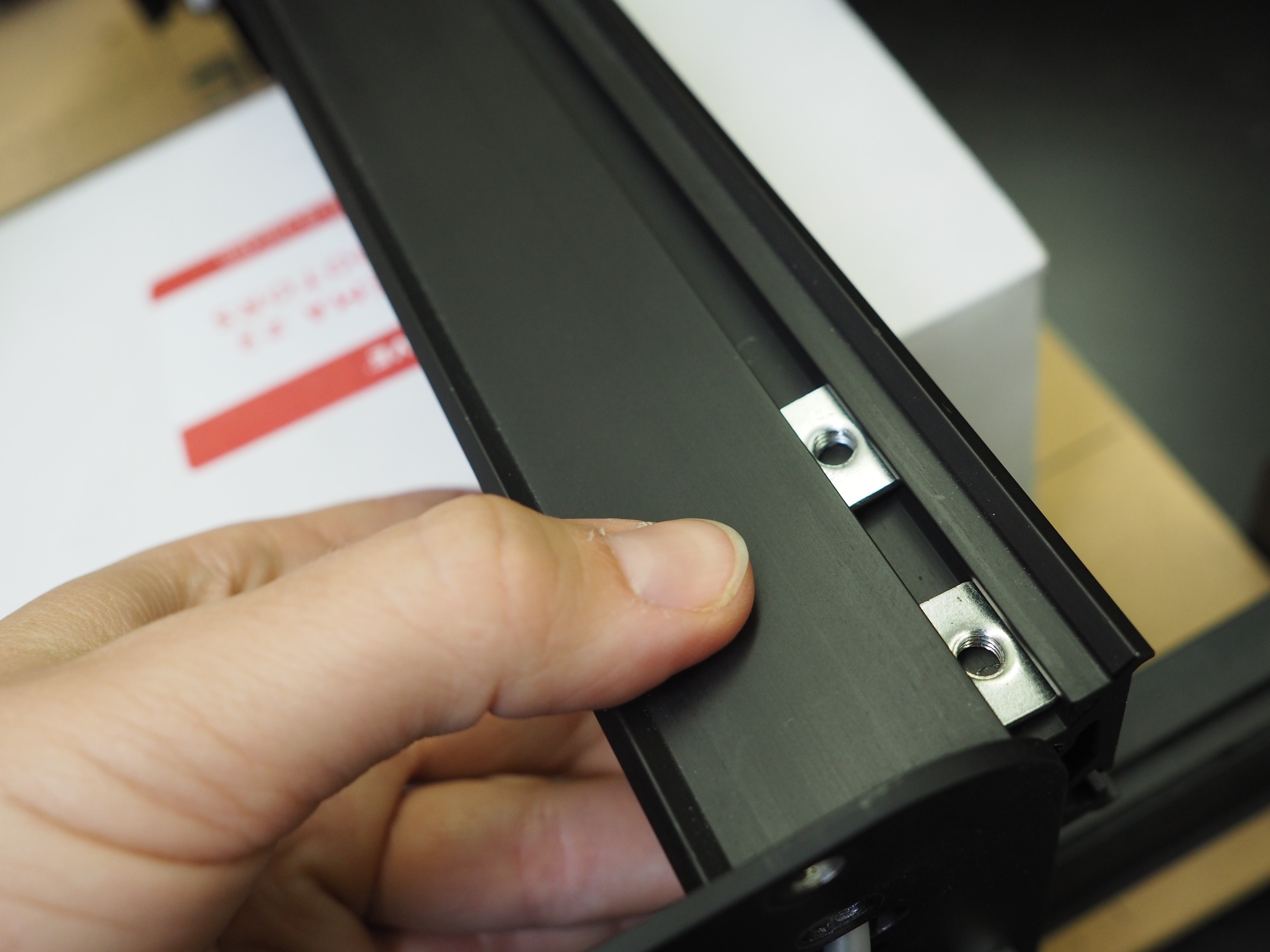
Make sure you remove the two pre-assembly t-slot nuts from the gantry. You’ll need to reinstall them on the new rail.
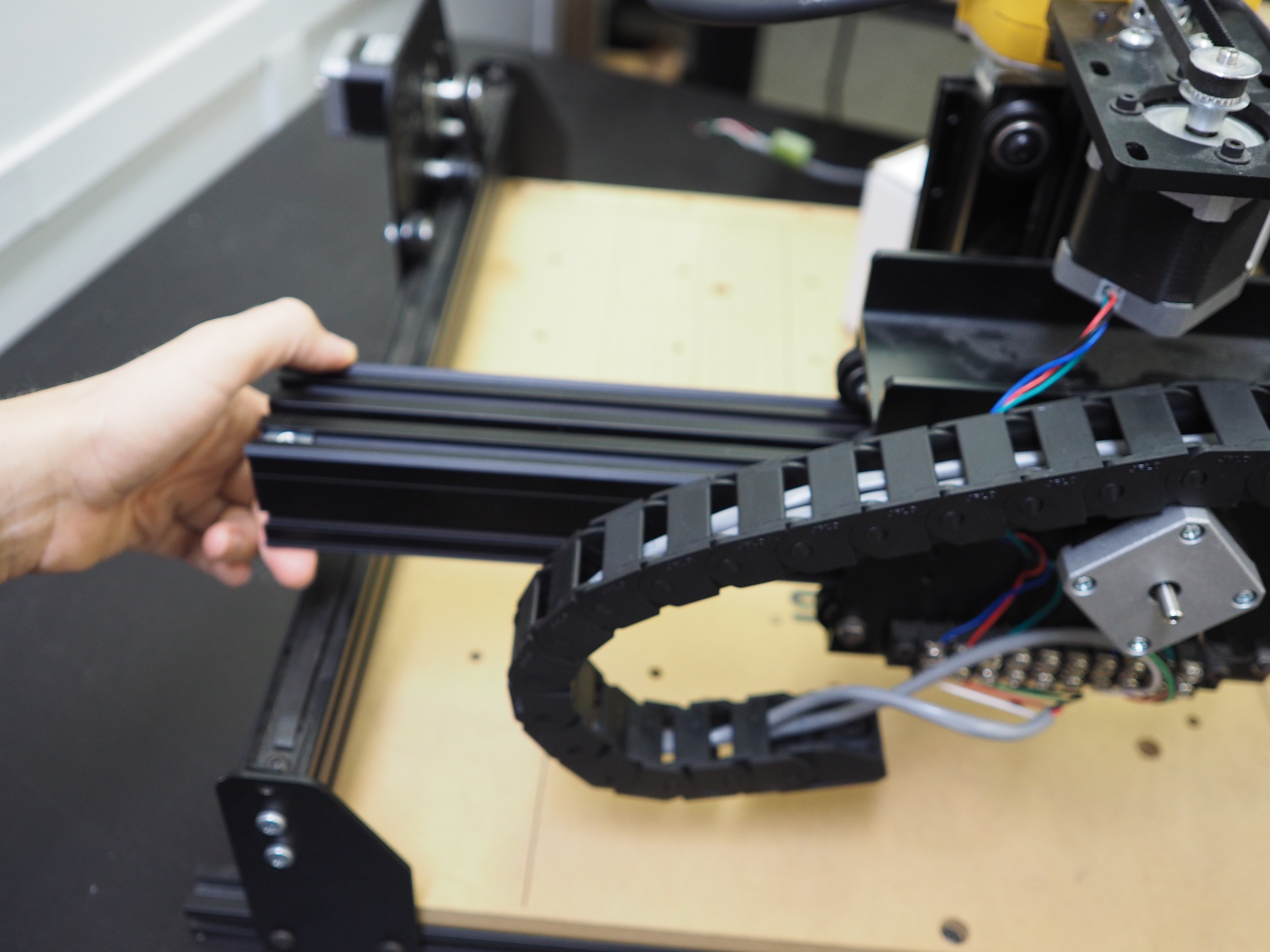
Next, remove the four screws holding the rails in place on the left side of the machine. You will need to hold the last rail with your hand while you unscrew the final screw.
When you are finished with this step, your two gantry MakerSlide rails should be completely removed from the machine. The top drag chain will also be removed from the machine.
Note: If your X-Carve has homing switches you will need to flip over the homing switch on the x-carriage so that the lever is pointing down
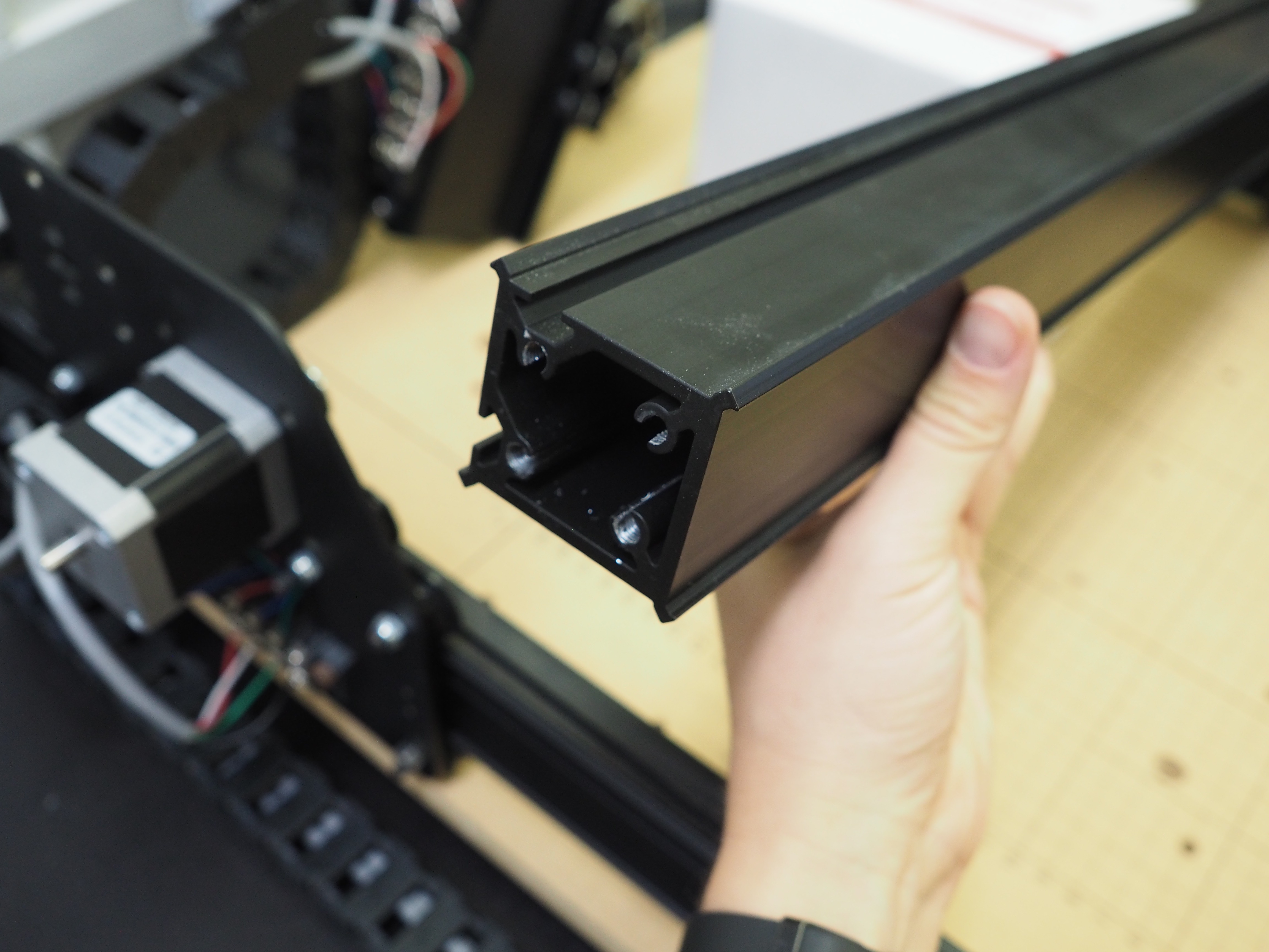
Ok, we’re halfway through! Now, it’s time to get your new wide MakerSlide rail. Make sure to position it so the X-Carve logo is on the right side of your machine, facing the front of the machine. The two grooves on the MakerSlide should be on the top and back of the rail if you are viewing the machine from the front.
We are going to assemble the new gantry in the reverse way that we disassembled it. We are going to start with the left side of the machine first. Align the rail with the same holes on the left y-axis plate from which we just removed the old gantry screws. You can use the same box to hold the new rail in place while you screw in the new MakerSlide rail.
Make sure you install the drag chain bracket to the left y-axis plate using the back two screws on the rail.
Now it’s time to add the x-carriage back onto the gantry. Align the V-wheels on the new rail. If possible, align the belting underneath the smooth idlers as you slide the carriage back onto the rail. This way the belting is in place and ready to go when the carriage is all the way on the rail.
Make sure the spindle is facing the front of the machine.
Slide the x-carriage onto the rail and move it far enough onto the rail so you can position the box underneath the rail on the right side of the machine, where the gantry is not secured to the plate yet.
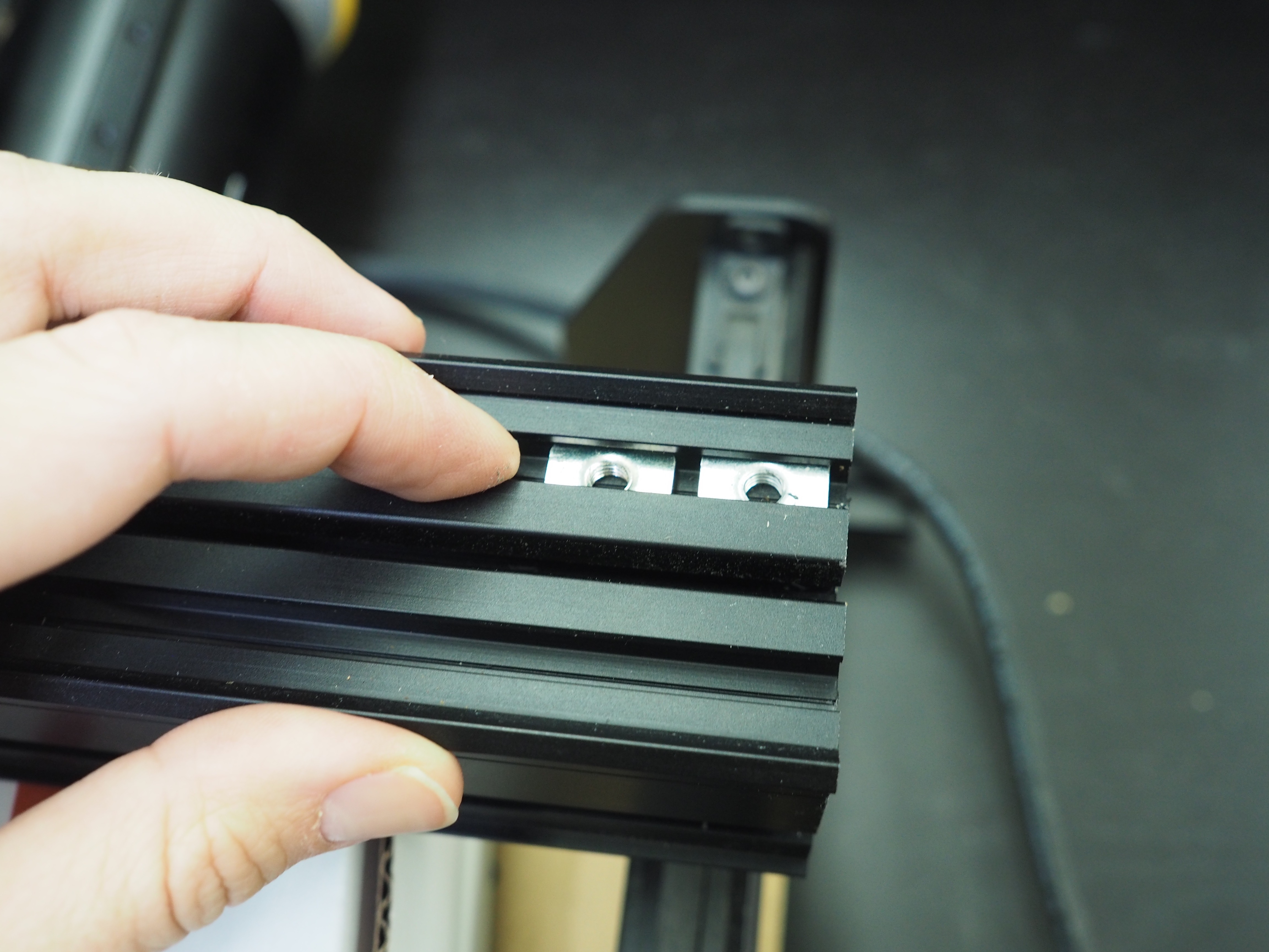
Before we forget, let’s add in the pre-assembly t-slot nuts to the top of the wide MakerSlide. Remember to insert them with the protruding part pointing down, so the flat part of the nut is on the top of the rail.
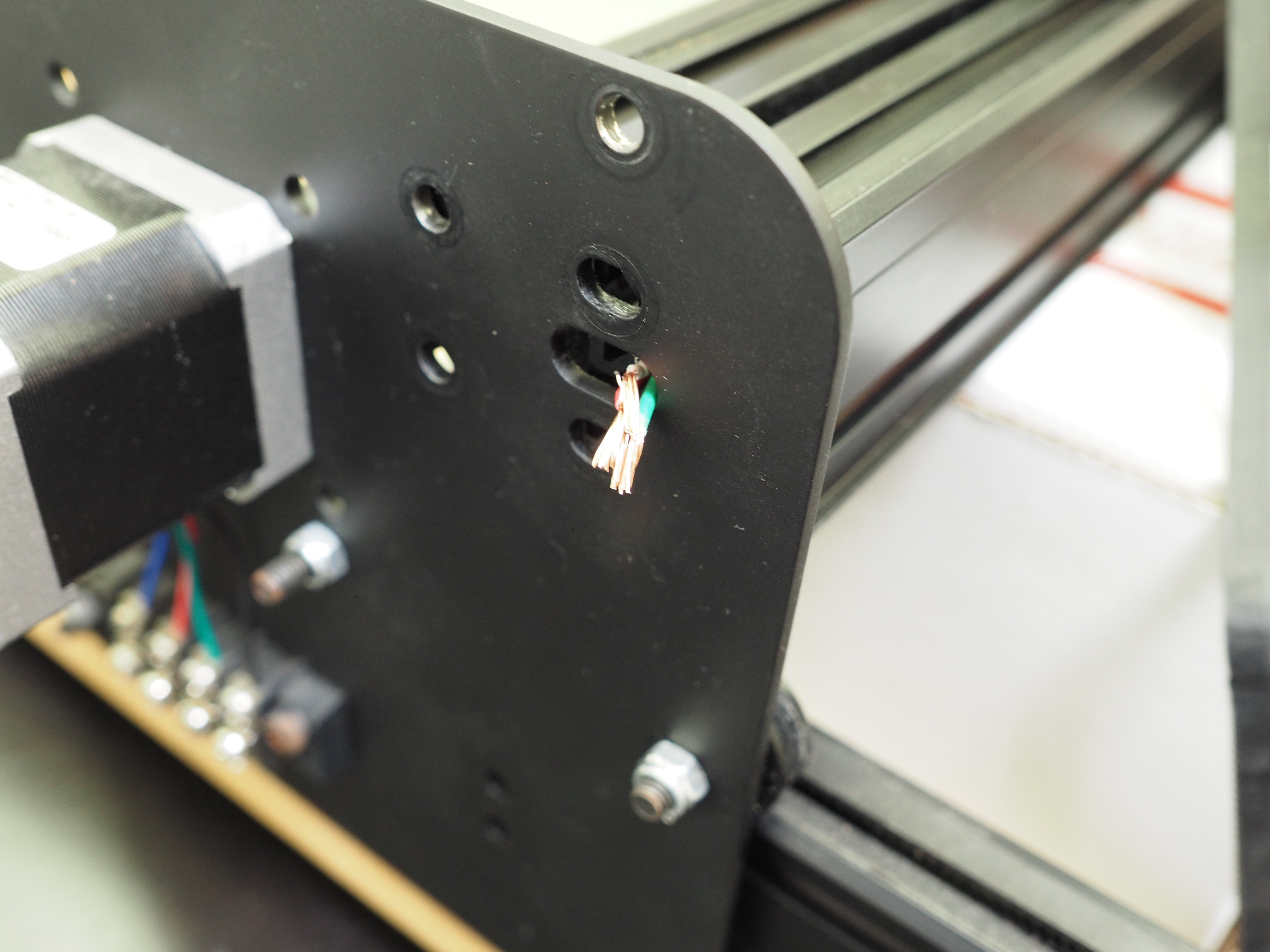
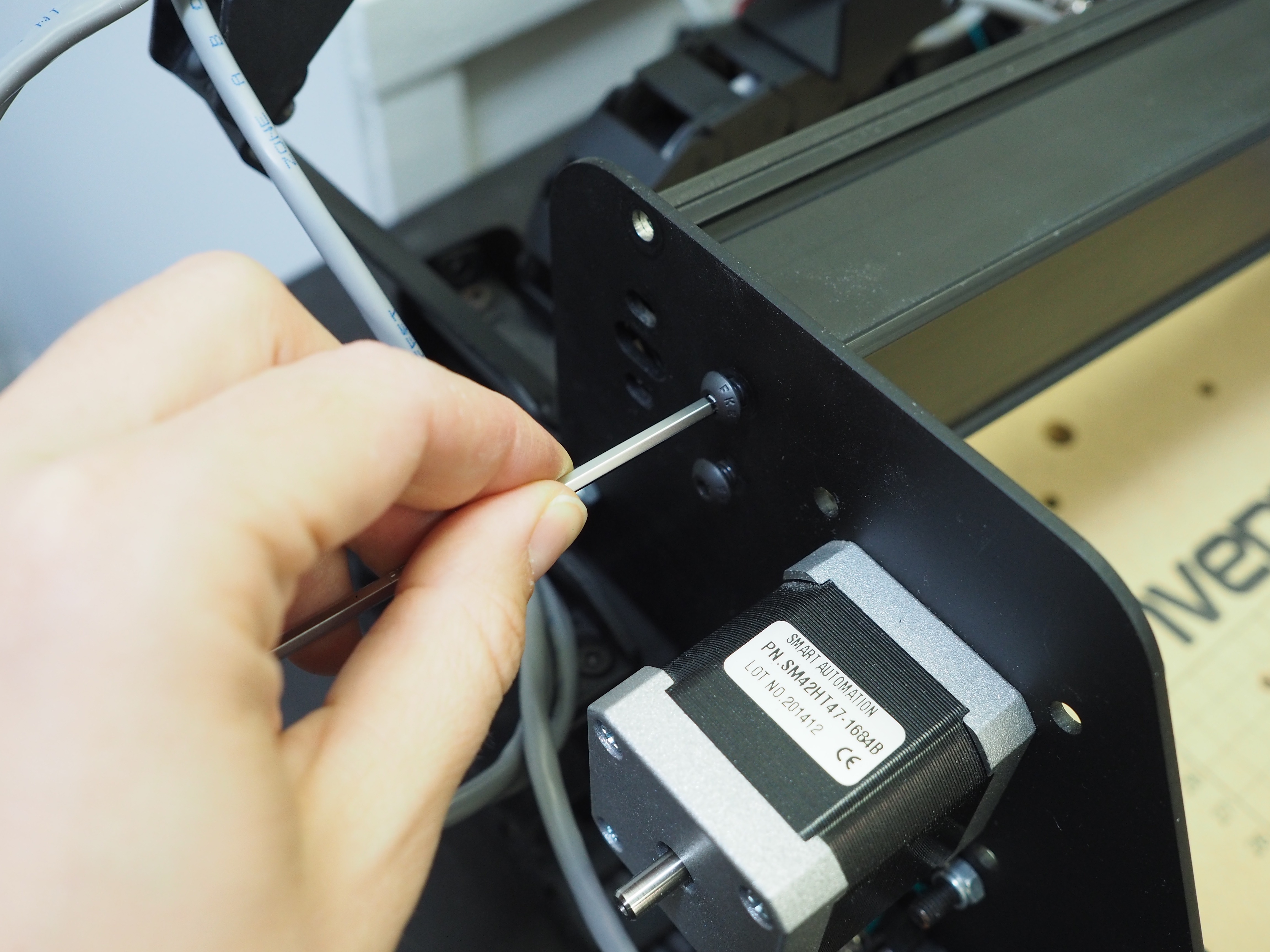
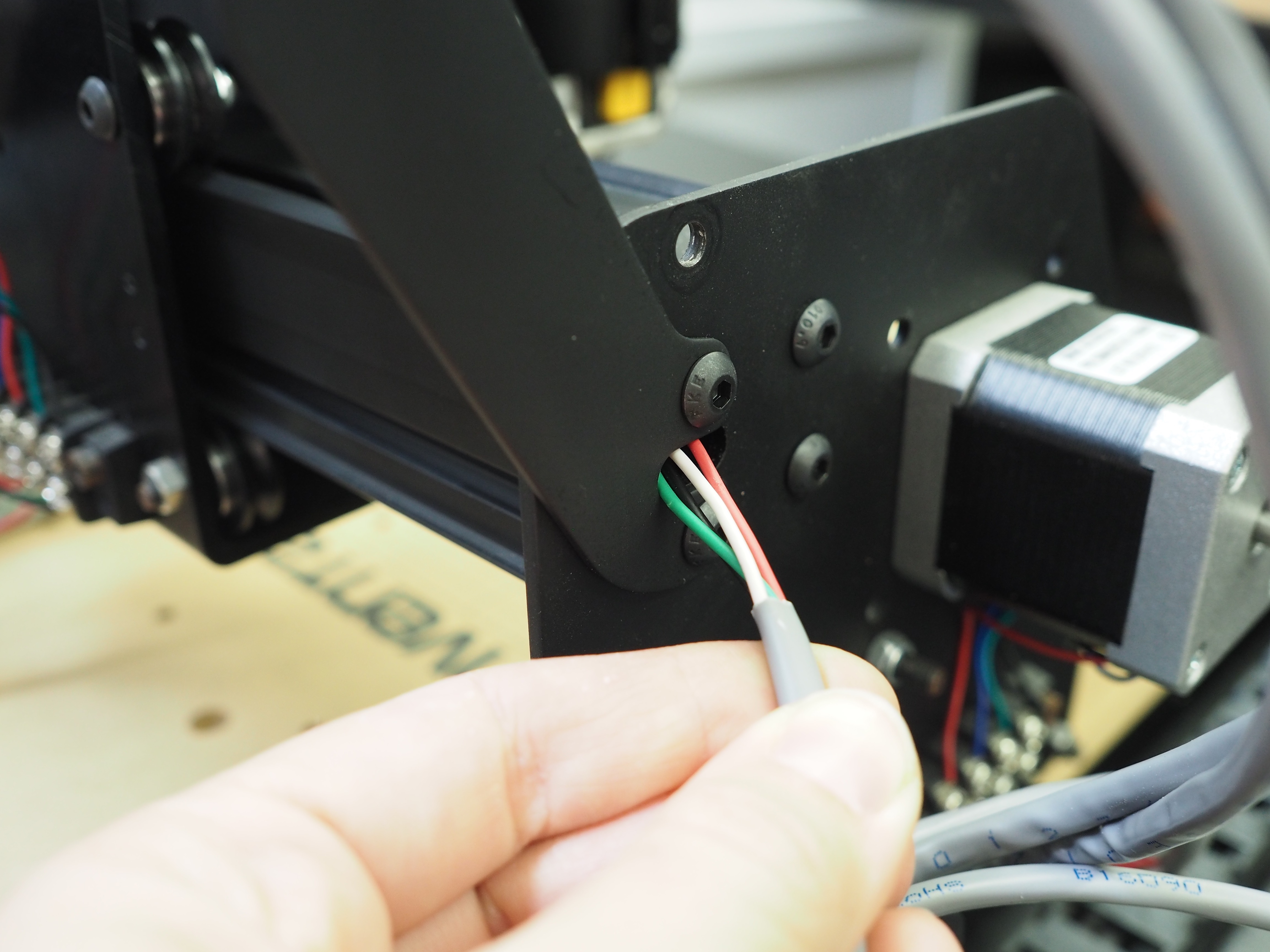
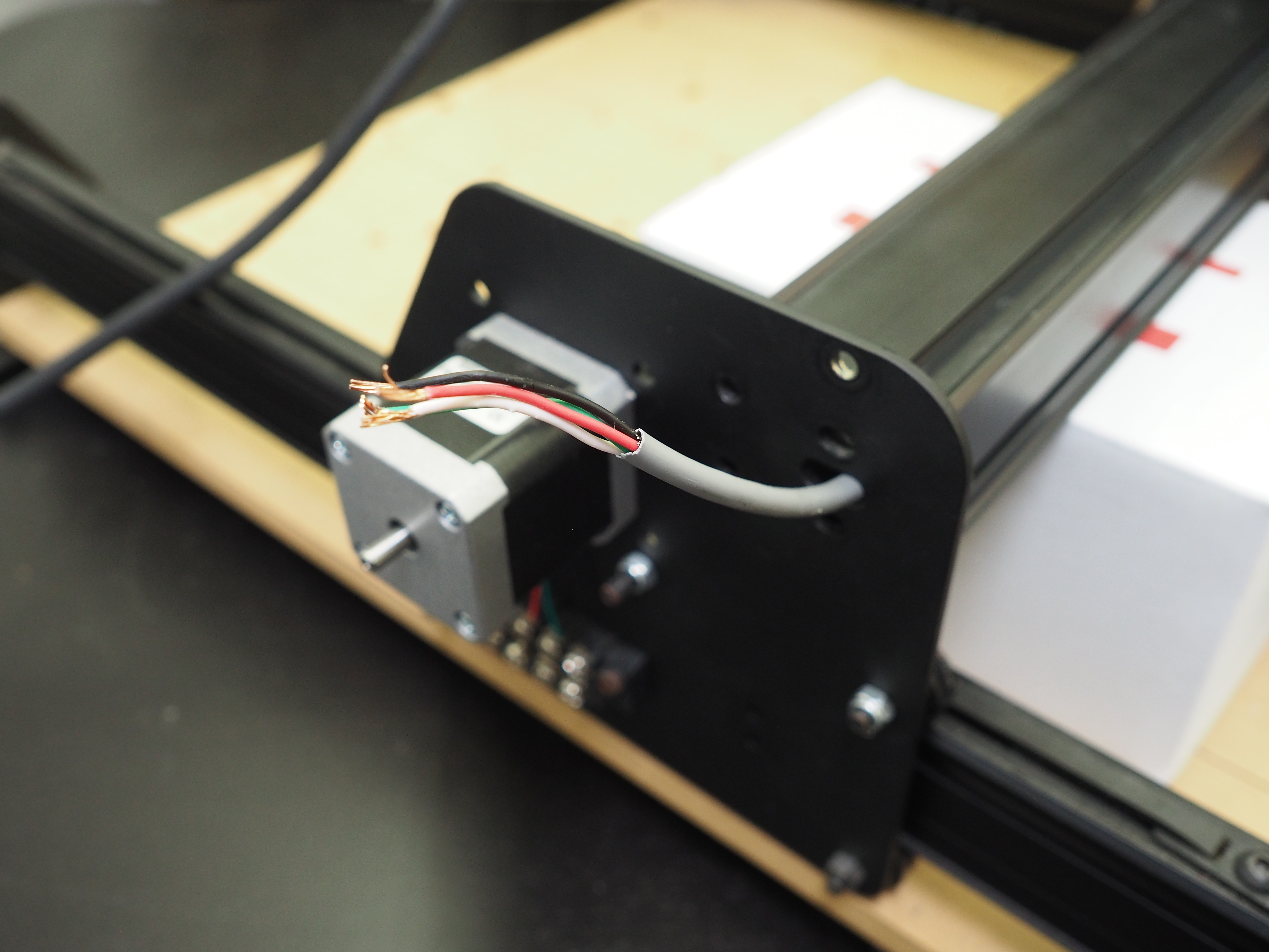
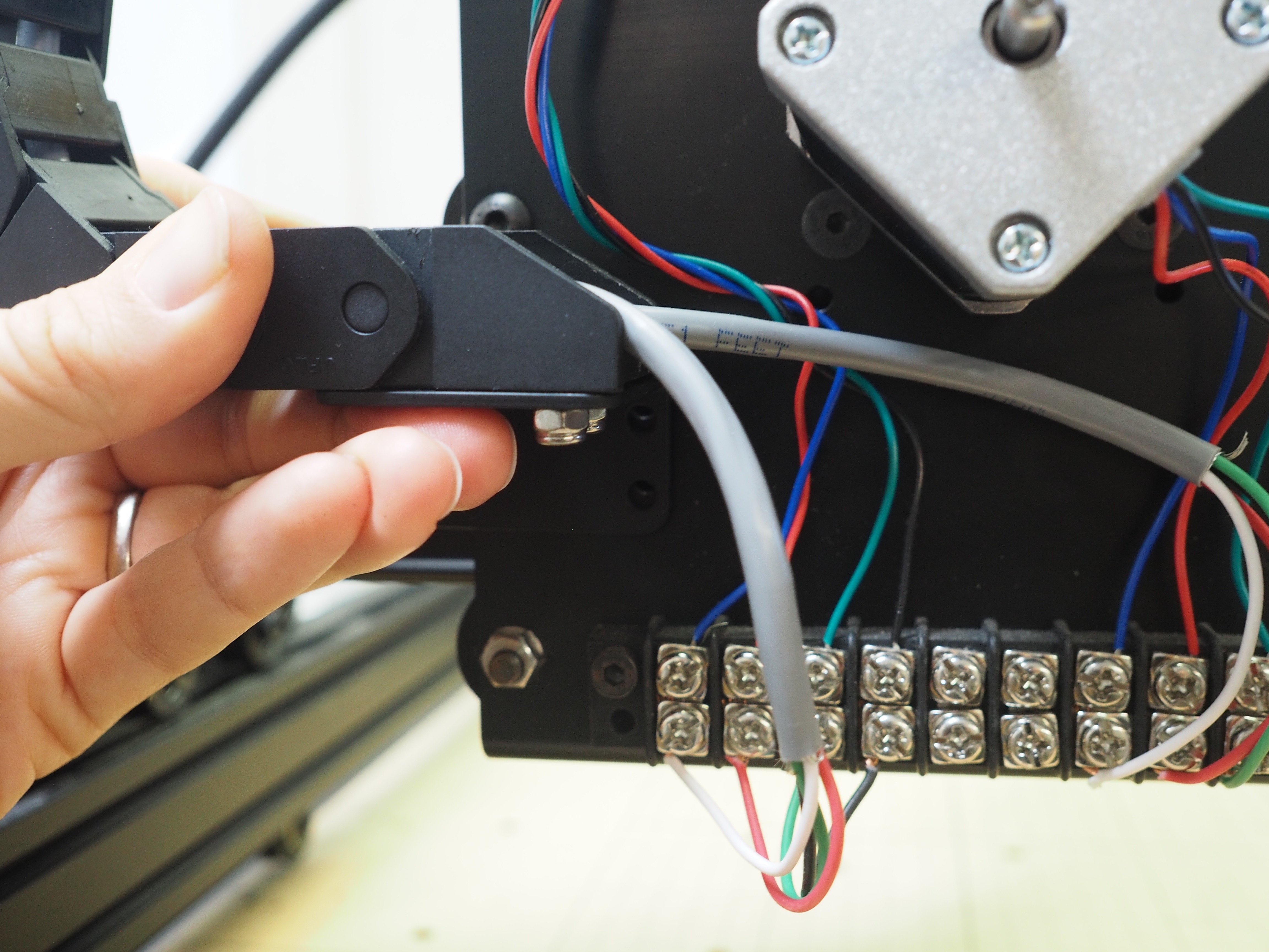
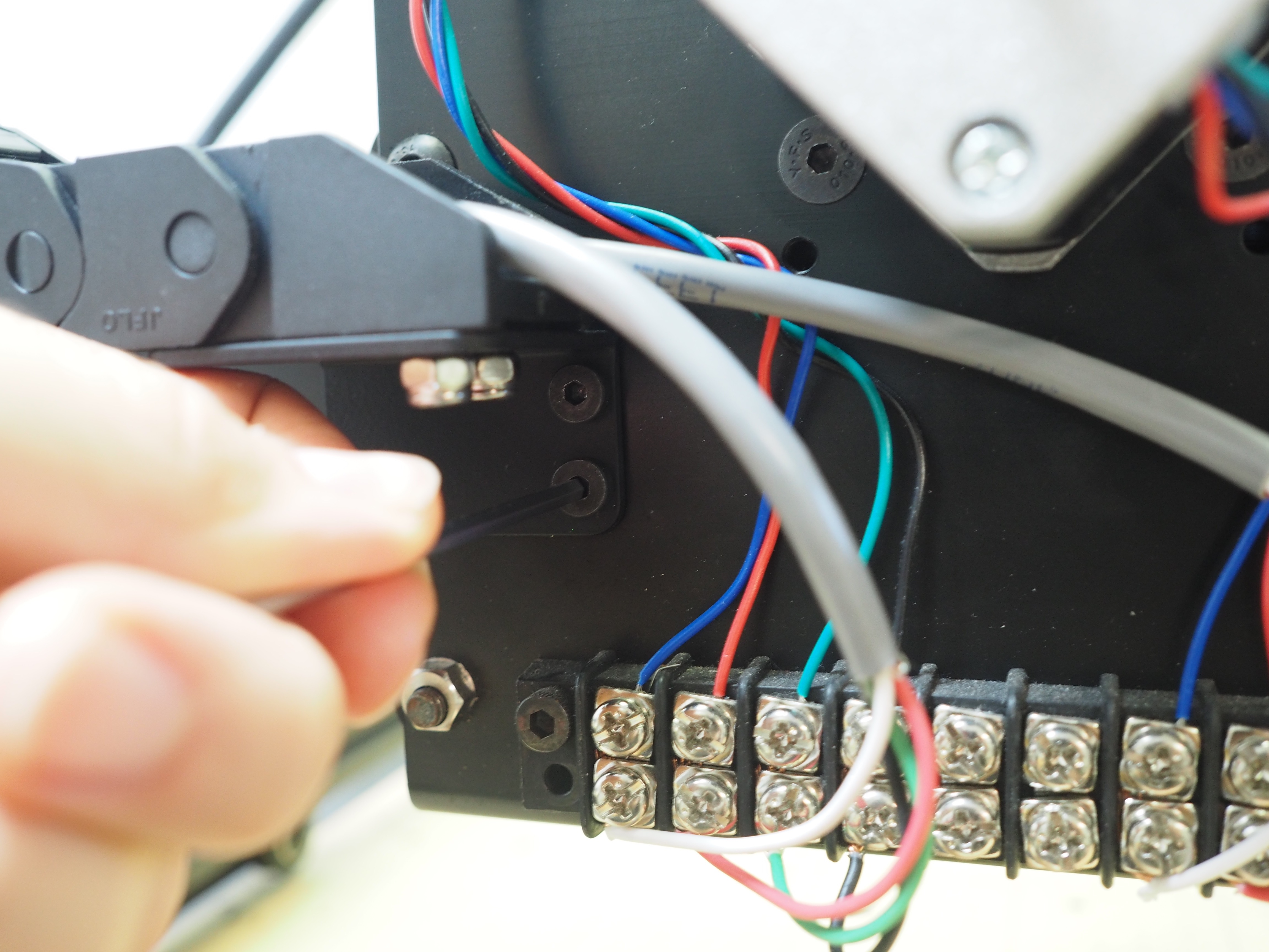
Next, thread the right y-axis stepper motor wire back through the gantry. Be careful not to damage the ends of the wire when inserting it through the MakerSlide. Do not pull the wire all the way through the MakerSlide. Position the end of the wire so it is flush with the end of MakerSlide rail. To make this next part easier, we suggest taping the ends of the wiring so you can thread it through the plate easier.
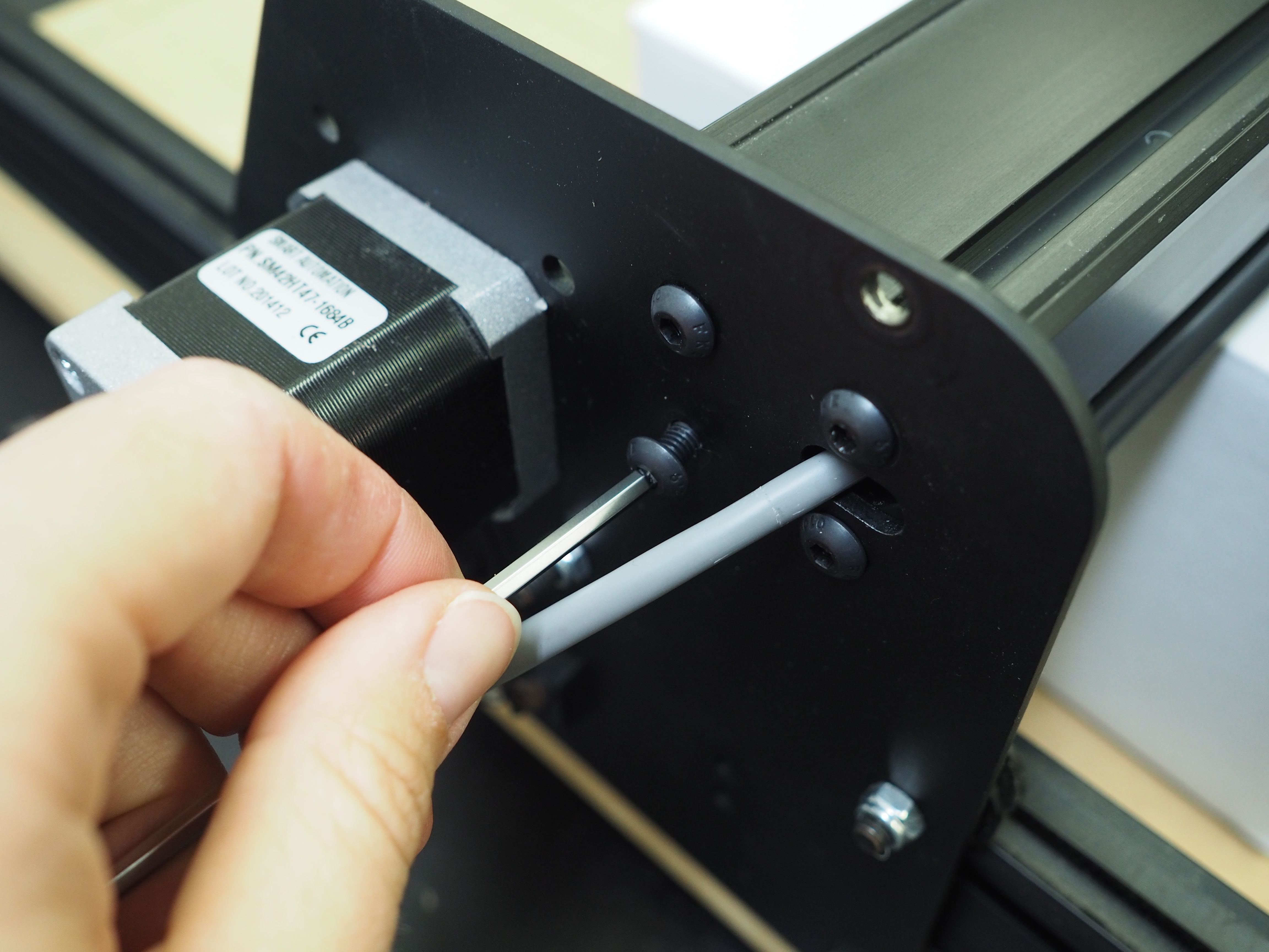
Slide the right side y-axis plate into place near the wide MakerSlide. Try aligning the wire with the oblong shape on the y-axis plate.
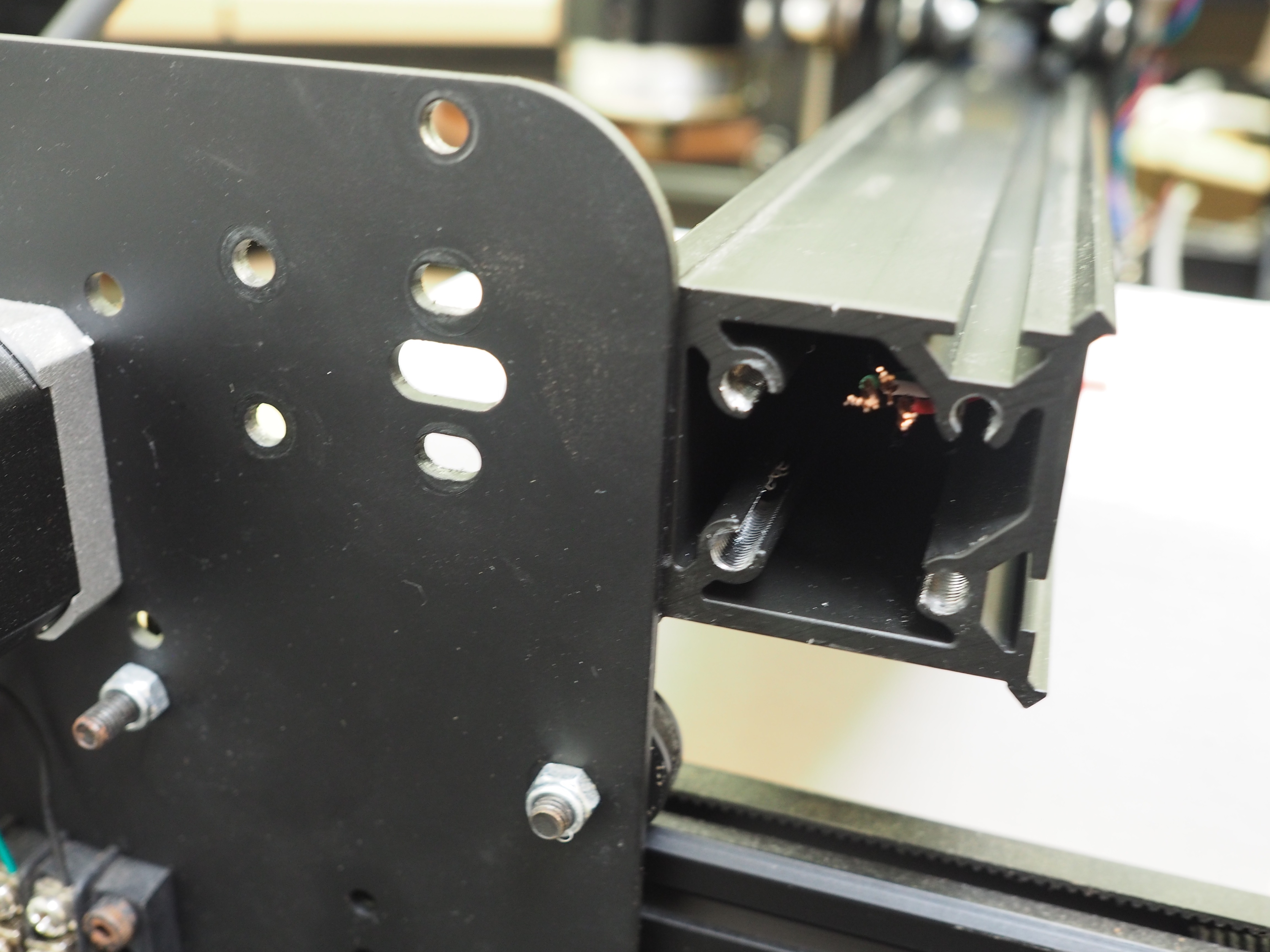
This next part is tricky. Again, we recommend taping the ends of your wiring to make it easier to thread the wires through the holes on the plate (the photos do not reflect this).
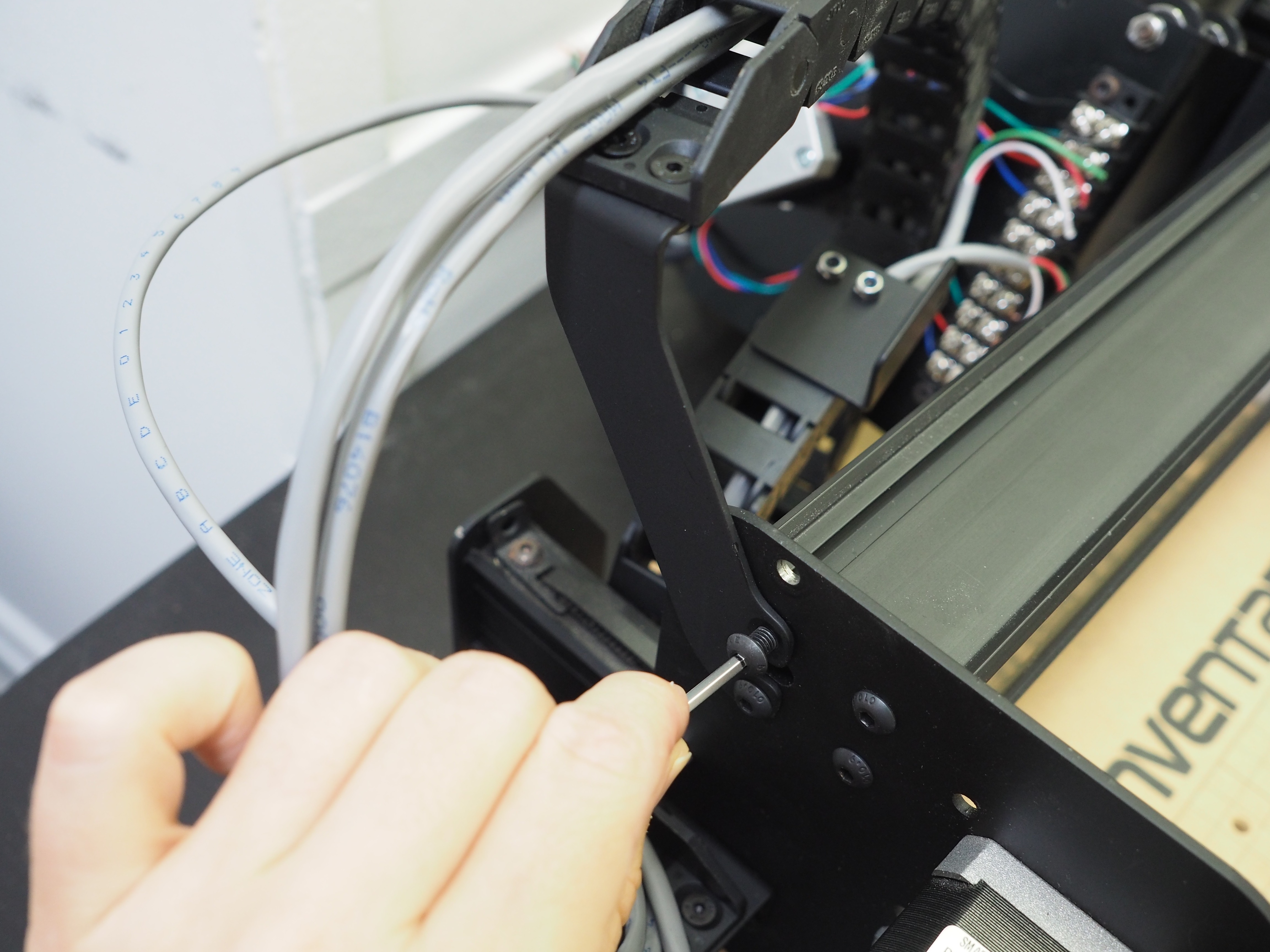
Position the right y-axis plate so the holes line up with the holes on the plate. You can try to push the wires through the oblong hole, but you will likely need a pair of tweezers to pull the wires through the plate. If you have taped the ends of your wires, it should be easier to grab the wires and pull them through. Be gentle so you don’t damage the insulation on the outside of the wires.
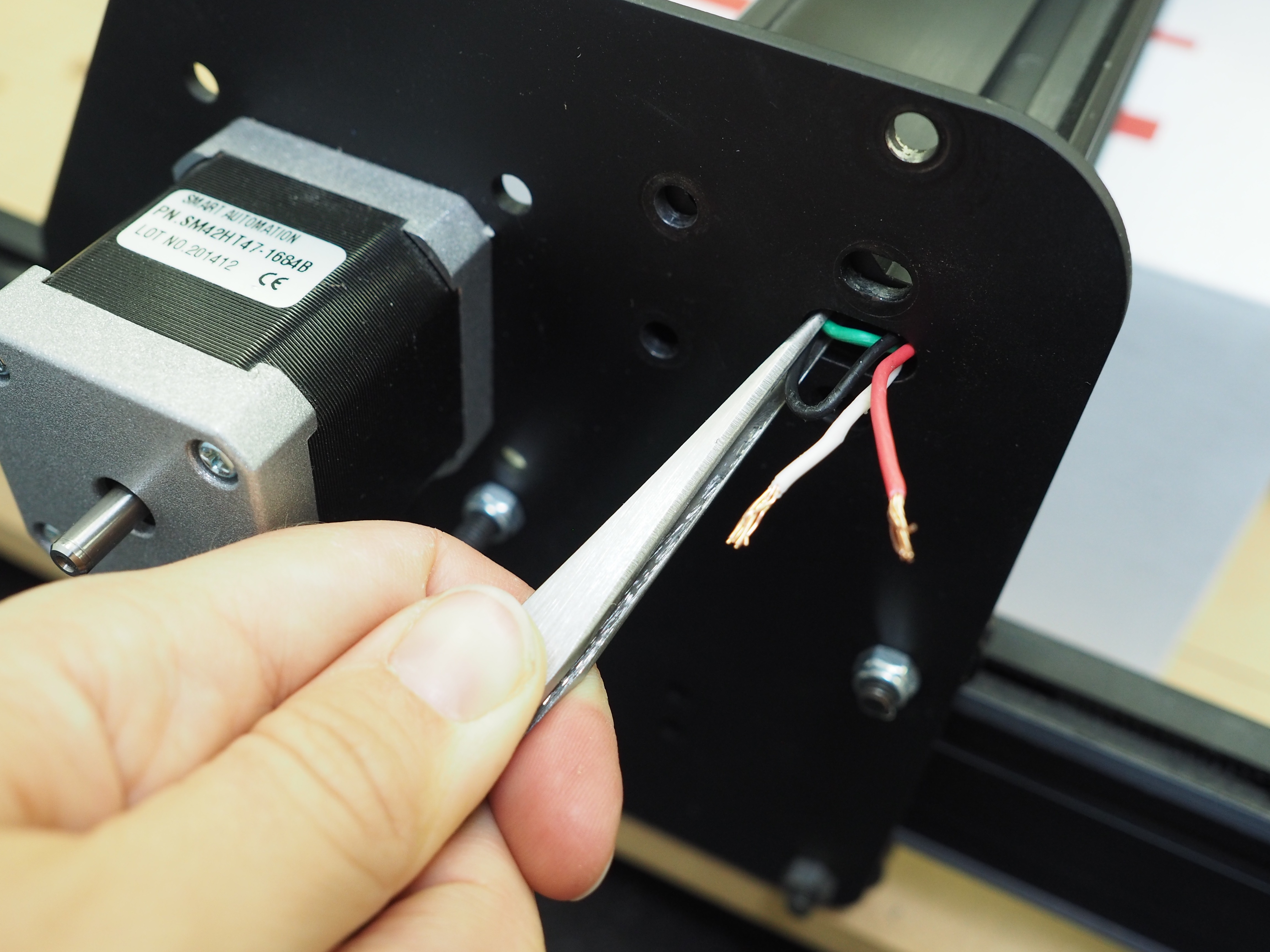
When the wire is fully through, check the insulation for any damage. Wrap any exposed wires with electrical tape so you don’t have a faulty connection. Rewire your stepper motor with the same configuration as before.
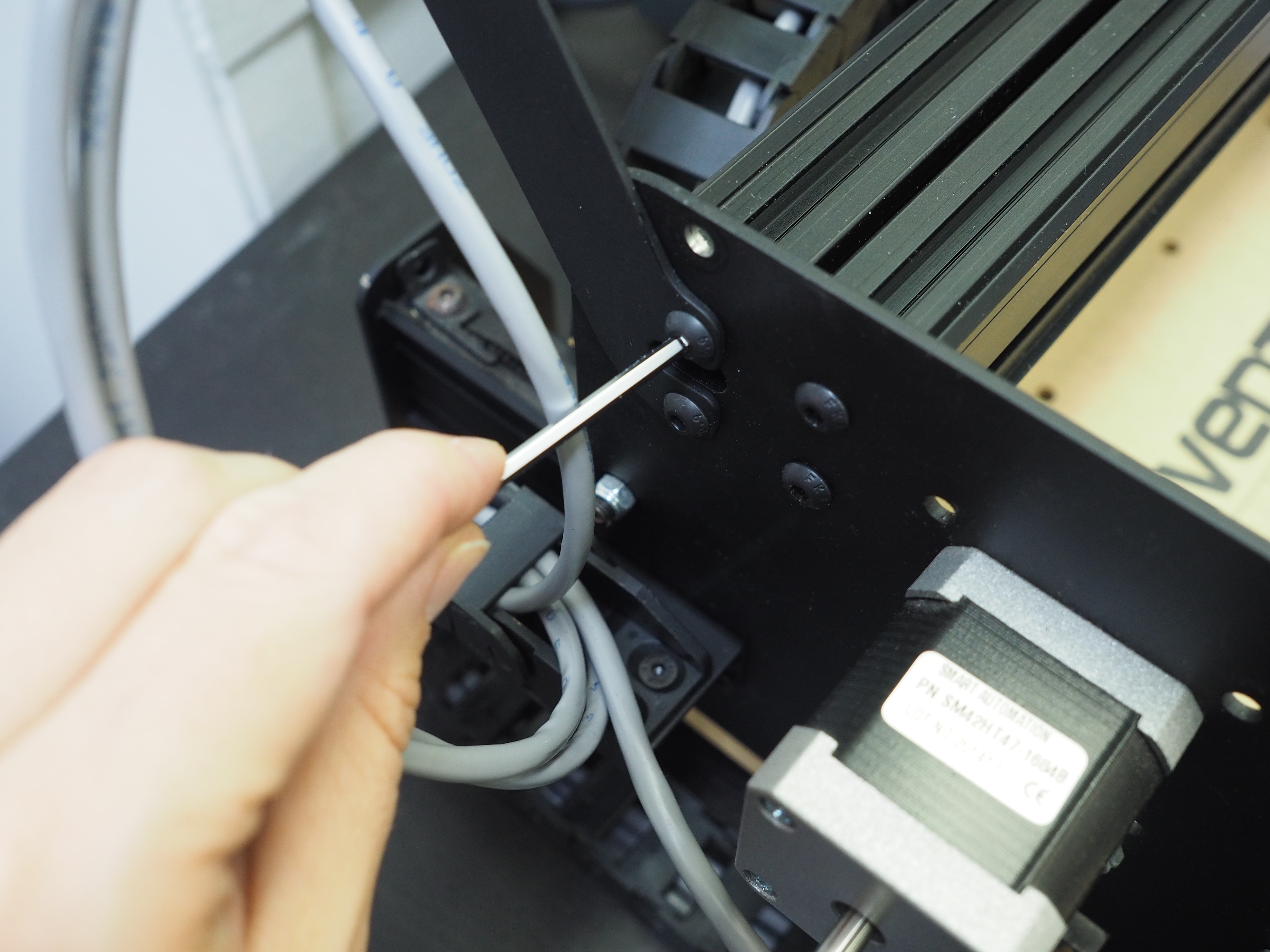
When the wiring is complete, secure the new wide MakerSlide rail in place using the four button head caps screws from the original rails.
The rail is now installed! You can remove the box supporting the underside of the rail.
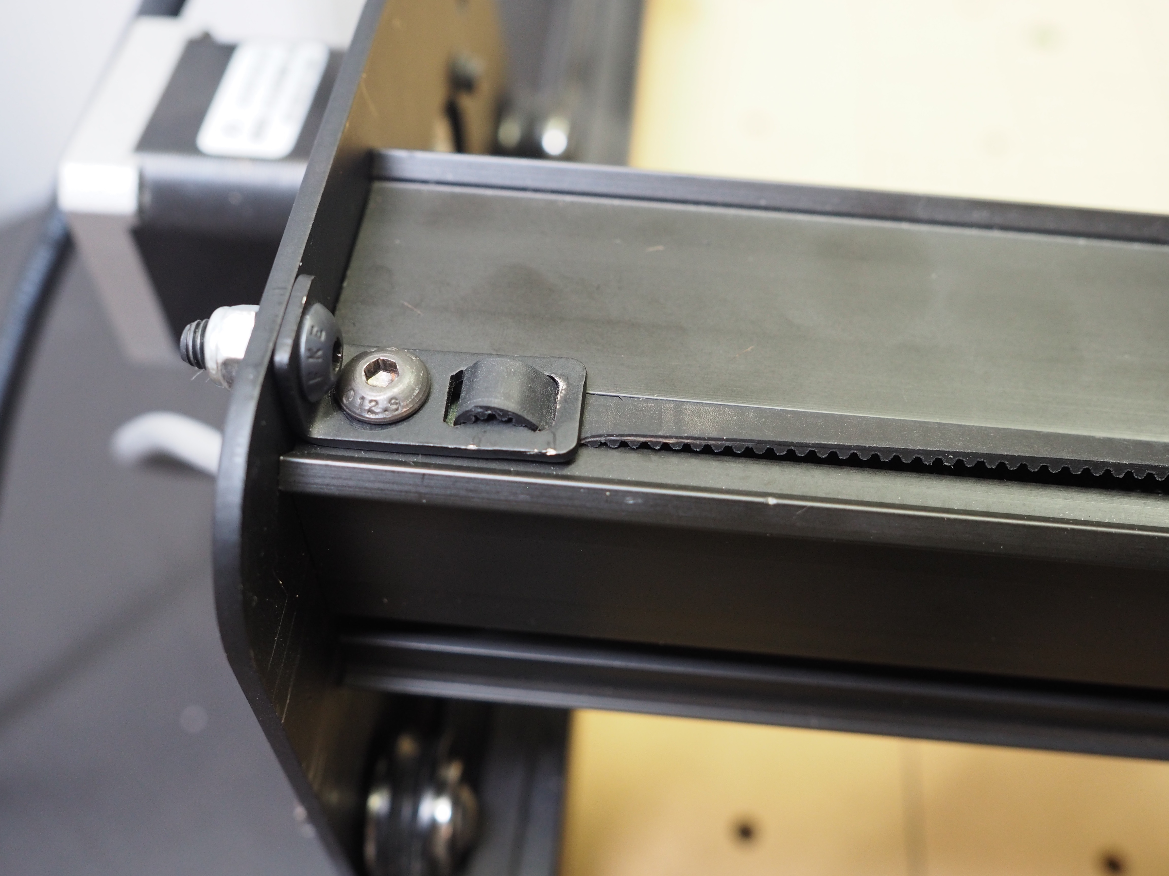
Next, we need to reinstall the belting. Start on the left side of the machine, and install the left belt clip. When inserting the shorter screw into the t-slot nut, don’t tighten it down all the way. The t-slot nut should still be able to move once the screw is installed partway.
You should not install the Nylock nut so both the head of the screw and the nut are flush on either side of the plate. The nut will be used for adjusting the belt tensioning after the machine is fully assembled, so we will want to make sure we can adjust the tension as necessary. The nut should be flush against the outside of the plate, but the head of the screw should still have space before the edge of the plate.
Your belting should still properly installed on the pulley. Take the time to make sure it is positioned properly underneath both smooth idlers before continuing.
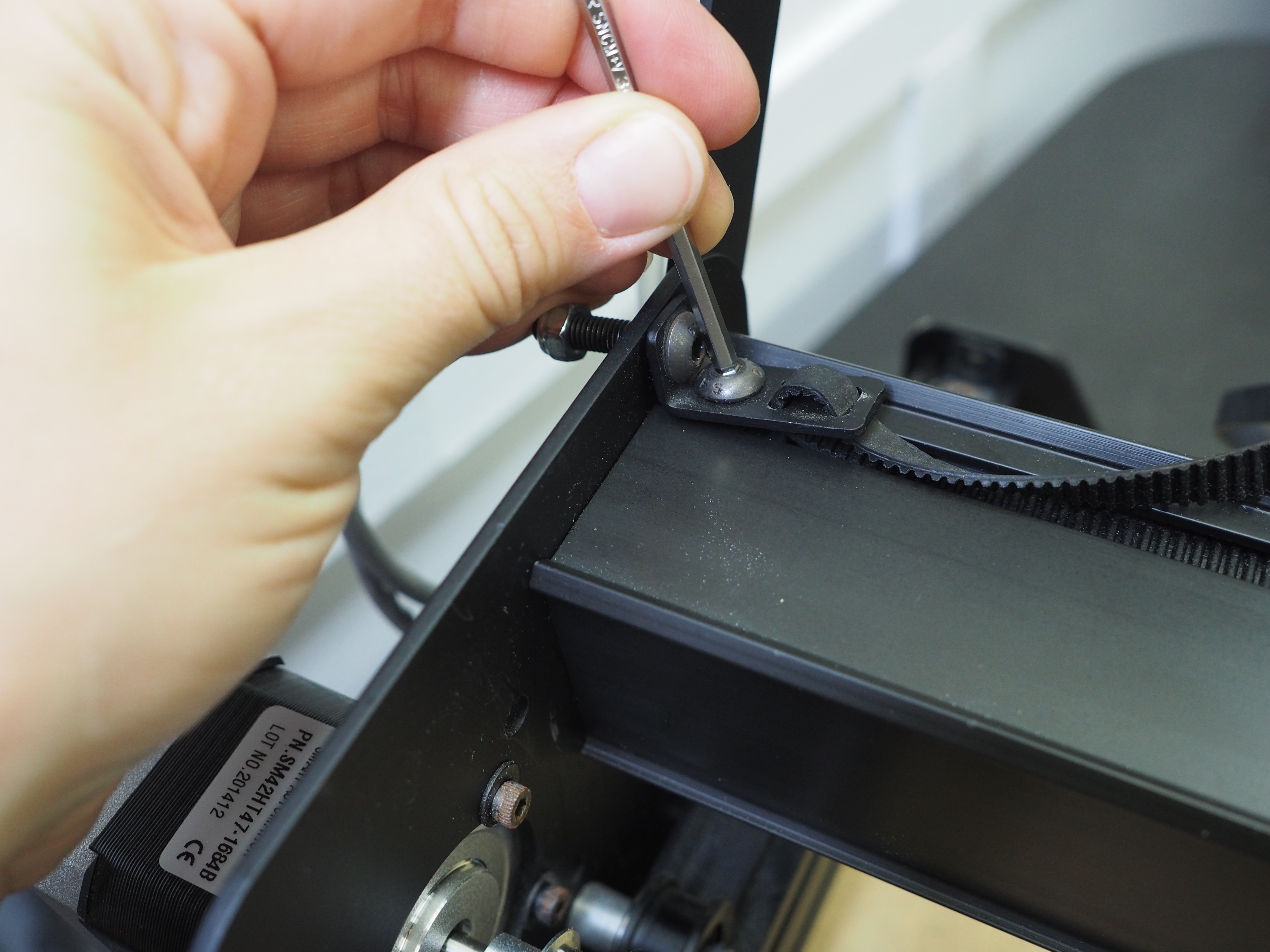
Working on the right side of the machine, install the smaller screw on the bottom part of the belt clip partially into the pre-assembly t-slot nut on the rail. The screw should be secured in the t-slot nut but you should still be able to slide the belt clip. Next, insert the longer screw into the hole on the right y-plate. Tighten the nylon locking nut on the long screw from the other side of the y-plate. Once the screw is tightened flush to the y-axis plate, finish tightening the smaller screw into the t-slot nut so the clip is fully secured.
The final step is reattaching the drag chain bracket to the x-carriage. Use the original screws to reattach the drag chain bracket to the x-carriage.
Before operating your machine again, make sure you check your belt tensioning using this video. You should be able to use the screw and nylock nut on the left side of the machine to properly set the belt tension.
Congratulations! Your new wide MakerSlide is now fully installed!
Next Step: X-Controller