X-Controller Usage
Usage Instructions
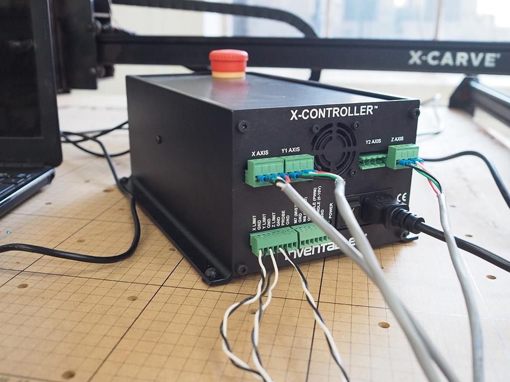
Congratulations on assemblying your new X-Controller, now let’s put it to use!
There are two options you can choose to take when putting this on your machine. Option one keeps your same wiring setup, but requires you to make some changes to the main controller board. Option two requires a new length of stepper motor cable and takes full advantage of the fourth stepper driver chip.
Option 1 - No New Wires
- Prepare Controller Board
- Wire Stepper Motor Cable
This is the easiest and quickest way to get going with your X-Controller. With this option you won't need to make any changes to your machine, but you will need to change the amount of current running to your y axis to get the most out of your two y motors.
Prepare Controller Board
As mentioned in the Install Controller Board step of the assembly instructions, you'll simply need to increase the potentiometer on your y-axis.
Wire Stepper Motor Cable
Remove the stepper motor cable from your gShield. Wire the cable into the green terminal block plugs and plug them into the corresponding spots on the X-Controller.
Option 2 - New Wires
- Unwire
- Wire New Stepper Motor Cable
- Optional Upgrades
This option takes a little bit of rewiring, but you end up with each motor getting its own dedicated stepper driver chip.
Unwire
Start by removing the drag chain end on the left side of the machine to gain access to the terminal block below the stepper motor. Remove the stepper motor cable from the top screws of the terminal block and separate the two stepper motors.
Wire New Stepper Motor Cable
Wire the left stepper motor to the left terminal block and completely remove the small length of stepper motor cable that was joining the two y motors. Wire your new piece of stepper motor cable to the right terminal block. Route the cable through the drag chain and reattach the drag chain end. Wire the cable into the green terminal block plugs and plug them into the corresponding spots on the X-Controller.
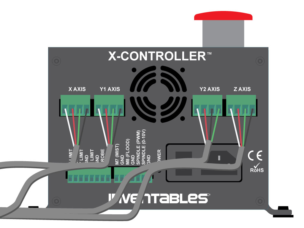
With two motors on the y axis facing each other, you'll need to flip one of the y pairs for the motors to move in the same direction. The diagram above shows the black and green wires flipped on Y2.
Optional Upgrades
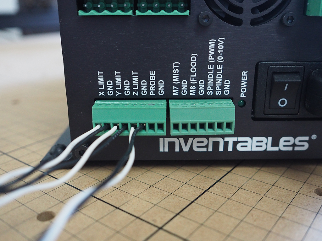
There are quite a few inputs and outputs on the x-controller that make adding upgrades easy. The limit switches, pictured above, now have their own dedicated signal and ground inputs. All conections are labeled clearly and we hope to offer additional upgrades to be used with the X-Controller sometime in the future.
Usage
- Buttons
- Easel Setup
Buttons
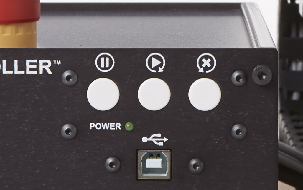 These three buttons allow you to start and stop, and reset a job while it's running. These are formally known as 'Feed Hold', 'Cycle Start', and 'Reset'.
Feed Hold:

If you've already started a job from your computer and need to pause it momentarily, you can click the feed hold button to stop the axes from moving. Note that if you are using a manually controlled spindle that this will not turn it off.
Cycle Start:

It's important to note that this will not start a job, though it will re-start one that has been paused. This only has an effect when the feed hold button has been pressed first.
Reset:

If, after pressing the feed hold button, you want to scrap the current job and start a new one, you can press the reset button. This will return the X and Y axes to home and keep your set home position. This button will only work if you've pressed the feed hold first.
Easel Setup
Head over to the Easel Setup Walkthrough to change any necessary grbl settings.
Spindle Control
For all AC spindles, you can use the PWM signal from the X-Controller to activate a relay to turn the spindle on and off. When going through the machine setup, select the Dewalt 611 and the max RPM will be set to 1. The PWM signal will now act like a simple enable on/off output.
For DC spindles such as the 300W Quiet Cut spindle, you'll need to wire the PWM signal and GND to the spindle speed controller PWM screw terminals. Make sure you move the jumper on the speed controller to the right position, closest to the PWM screw terminals. Go through the Easel machine setup, clicking on "Other" and set your Max RPM to 12000 (this may be different for other DC Spindles). Wiring diagrams will be added shortly to help with clarification.
Troubleshooting
- Won't Turn On
- Limit Switches
- Won't Connect
This video is intended to help those with opening back up their X-Controllers for troubleshooting.
My X-Controller won't turn on!
Check to make sure your e-stop button is pulled out and not engaged.
My limit switches don't work!
Check that the ribbon connectors are fully pushed into the mating connectors.
My X-Controller won't connect to my computer!
Just like the gShied/Arduino, for Windows users you'll need to download the Arduino IDE to get the necessary drivers. For more information, check out the Drivers section of the X-Carve instructions.
Get Arduino Software