Y Plates
You’ll need these parts to assemble your Y-Plates:
| Core Components Kit | ||
| SKU | Name | Quantity |
| 30525-01 | Gantry Side Plate (Y-Plate) | 2 |
| 25197-01 | Smooth Idler Wheel Kit | 4 |
| 25203-01 | Dual Bearing V-Wheel Kit | 8 |
| 25286-22 | Button Head Cap Screw M5 x 35mm | 4 |
| 25286-21 | Button Head Cap Screw M5 x 25mm | 8 |
| 30265-04 | Nylon Insert Lock Nut M5 | 8 |
| 30158-01 | Eccentric Nut M5 | 4 |
| 25287-08 | Flat Washer M5 | 8 |
| 25312-23 | Aluminum Spacer 5.1mm ID 9.5mm OD 9.5mm LG | 4 |
1. Smooth Idlers
You’ll mount two smooth idlers to each Y-Plate. These are the mounting holes:

To mount a smooth idler to your Y-Plate slide it onto a 35mm screw followed by an aluminum spacer. Remember that the smooth idler is an asymmetrical part.
Insert the screw through the Y-Plate and fasten it with a hex nut on the other side. Tighten the nut with moderate force.


Repeat this process for the other smooth idler:

2. V-Wheels
Each Y-Plate has four holes for V-Wheels. Just like the X Carriage there are two sizes of holes that accept V-Wheels; the smaller holes are for V-Wheels with nylock nuts and the larger holes are designed to accept V-Wheels with eccentric nuts.

Start by installing the top two V-Wheels. Put a V-Wheel on a 25mm button head cap screw followed by a washer. Tighten a nylock nut on the other side of the plate:


Repeat with another 25mm screw, V-Wheel, washer and nylock nut.

Repeat the process for the bottom V-Wheels using eccentric nuts this time. Be sure to seat the shoulder of the eccentric nut flush in the hole.


Repeat with another 25mm screw, V-Wheel, washer and eccentric nut.

Before proceeding adjust the eccentric nuts to the open position.

Repeat everything you did with the other Y-Plate, but mirror the orientation of your parts. You should have two Y-Plates that look like this:

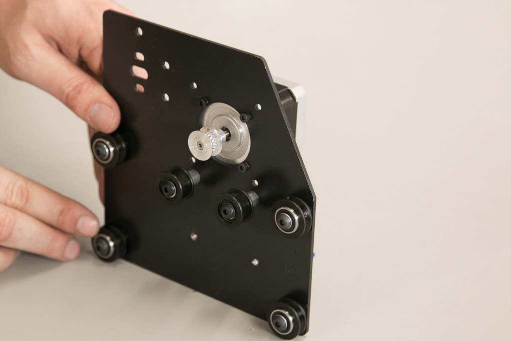
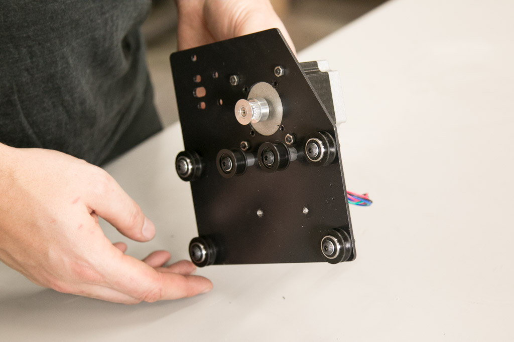
3. Y-Axis Motor Mounting
If you purchased a stepper motor kit with your X-Carve, click on your chosen type below to mount your motors.
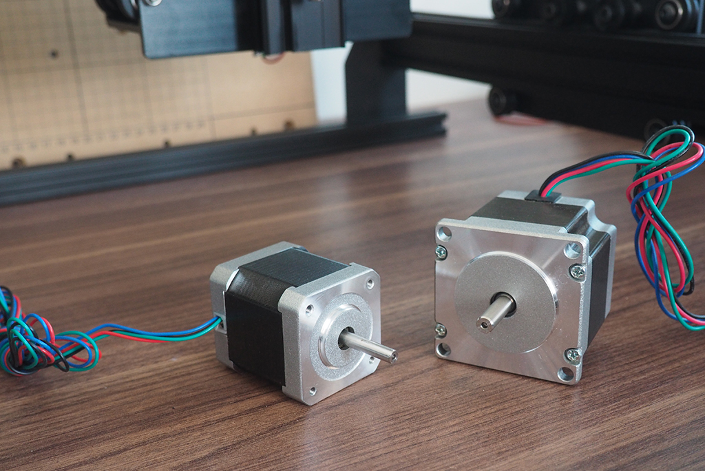
Nema 17
| NEMA 17 Stepper Motor Kit | ||
| SKU | Name | Quantity |
| 25253-01 | Stepper Motor NEMA 17 62 oz-in | 2 |
| 26054-01 | Aluminum GT2 Pulley 20T 5mm | 2 |
| 25285-31 | Socket Head Cap Screw M3 x 8mm | 8 |
| 25287-10 | Flat Washer M3 | 8 |


Nema 23
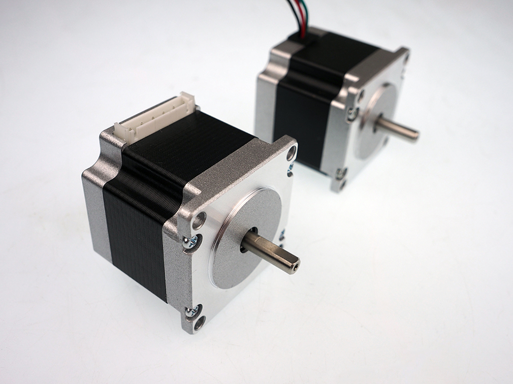
| NEMA 23 Stepper Motor Kit | ||
| SKU | Name | Quantity |
| 25311-04 | Stepper Motor NEMA 23 140oz-in | 2 |
| 26054-03 | Aluminum GT2 Pulley 20T 1/4in | 2 |
| 25285-36 | Socket Head Cap Screw M5 x 16mm | 8 |
| 25287-08 | Flat Washer M5 | 8 |
| 30265-04 | Nylon Insert Lock Nut M5 | 8 |


4. Mounting Drag Chain End (Left Plate)
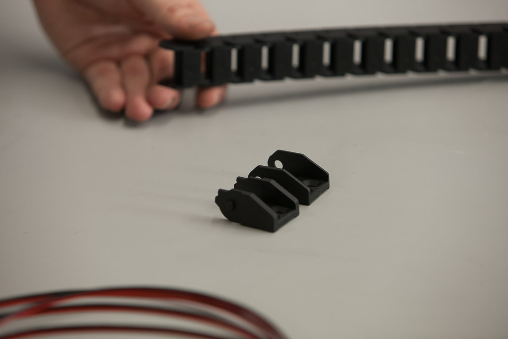
If you purchased a drag chain kit with your X-Carve, click below to mount your drag chain ends.
Drag Chain
| Drag Chain Kit | ||
| SKU | Name | Quantity |
| 30331-09 | Drag Chain Male End Link (attached) | 1 |
| 30554-01 | Flat Head Socket Cap Screw M4 x 10mm | 2 |
| 30265-03 | Nylon Insert Lock Nut M4 | 4 |
| 25286-24 | Button Head Cap Screw M4 x 10mm | 2 |
| 30586-01 | Drag Chain Angle Bracket | 1 |


5. Mounting Terminal Block (Both Plates)
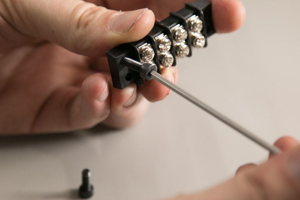
If you purchased a wiring kit with your X-Carve, click below to mount your terminal block.
Wiring
| Wiring Kit | ||
| SKU | Name | Quantity |
| 25306-01 | Terminal Block 4C | 2 |
| 25285-35 | Socket Head Cap Screw M4 x 14mm | 4 |
| 30265-03 | Nylon Insert Lock Nut M4 | 4 |


6. Mounting Y-Axis Limit Switch
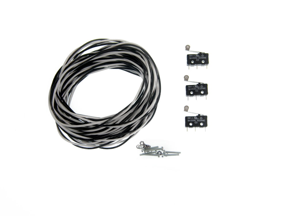
If you purchased a limit switch kit with your X-Carve, click below to mount your x-axis limit switch.
Limit Switch
| Limit Switch Kit | ||
| SKU | Name | Quantity |
| 30557-01 | Microswitch – Roller Actuator | 1 |
| 30544-02 | Pan Head Screw M2 x 14mm | 2 |
| 25284-09 | Hex Nuts M2 | 2 |
| 30555-02 | Split Lock Washer M2 | 2 |


