Wiring
1. Prepare Stepper Motor Wires
First you’ll trim the excess wire from each stepper motor and strip each wire of each stepper motor (16 in total). You’ll want about 1/4” of bare wire showing.

2. Secure Wires in Terminal Blocks
Next insert the stepper motor wires for the X and Z motors into the corresponding terminal blocks. To keep wiring consistent work from left to right and keep the order of red, blue, green and black.
X-Motor

Z-Motor

Right Y-Motor
Next insert the stepper motor wires for the right Y-Motor into the corresponding terminal block. To keep wiring consistent work from left to right and keep the order of red, blue, green and black.

3. Prepare Stepper Cable
Next cut the stepper cable to length.
| 500mm Machine | |
| Length | Quantity |
| 6 feet | 2 |
| 4 feet | 1 |
| 3 feet | 1 |
| 1000mm Machine | |
| Length | Quantity |
| 12 feet | 2 |
| 7 feet | 1 |
| 5 feet | 1 |
Strip one end of each piece of stepper cable. There is grey insulation around all four wires inside. Remove it as well as the foil, string and thin silver wire. You should be left with four wires; one black, one green, one white and one red.


Strip about 1/4” of each of these colored wires.

4. Secure Stepper Cable in Terminal Blocks
Take the shortest length of stepper cable and wire it to the terminal block on the right Y-Plate. Match red to red, white to blue, green to green and black to black.

Put the other end of this piece of stepper cable in to this hole and thread it through the X-Axis of the machine:

When you get the end through the same hole on the left Y-Plate strip it as before. Now you’ll twist these wires with the left Y-Motor wires. Twist them as follows: red to white, blue to red, green to green, and black to black. Insert them into the terminal block one pair at a time. When you’re done your left Y-Plate should look like this:

Ok, that was the hardest part of the wiring. Now you’ll wire the x-axis motor. Use one of the longest pieces of stepper cable and wire into the terminal block under the x-axis motor. Match red to red, blue to white, green to green and black to black. Repeat the process with the other long piece of stepper cable for the z-motor. When you’re done you should have something like this:

If you purchased a 24V or 48V spindle with your X-Carve kit now is a good time to attach the zip wire that will eventually power it. Pull the black and red wires away from each other and strip the ends leaving about 1/4” bare. Wire them into the bottom of the terminal block in the two spaces you left open. Use the left terminal for red and the right terminal for black.

Now you’ll wire the left y-axis motor. Use your last piece of stepper cable and wire into the bottom of the terminal block on the left Y-Plate in the order of red, white, green, and black.

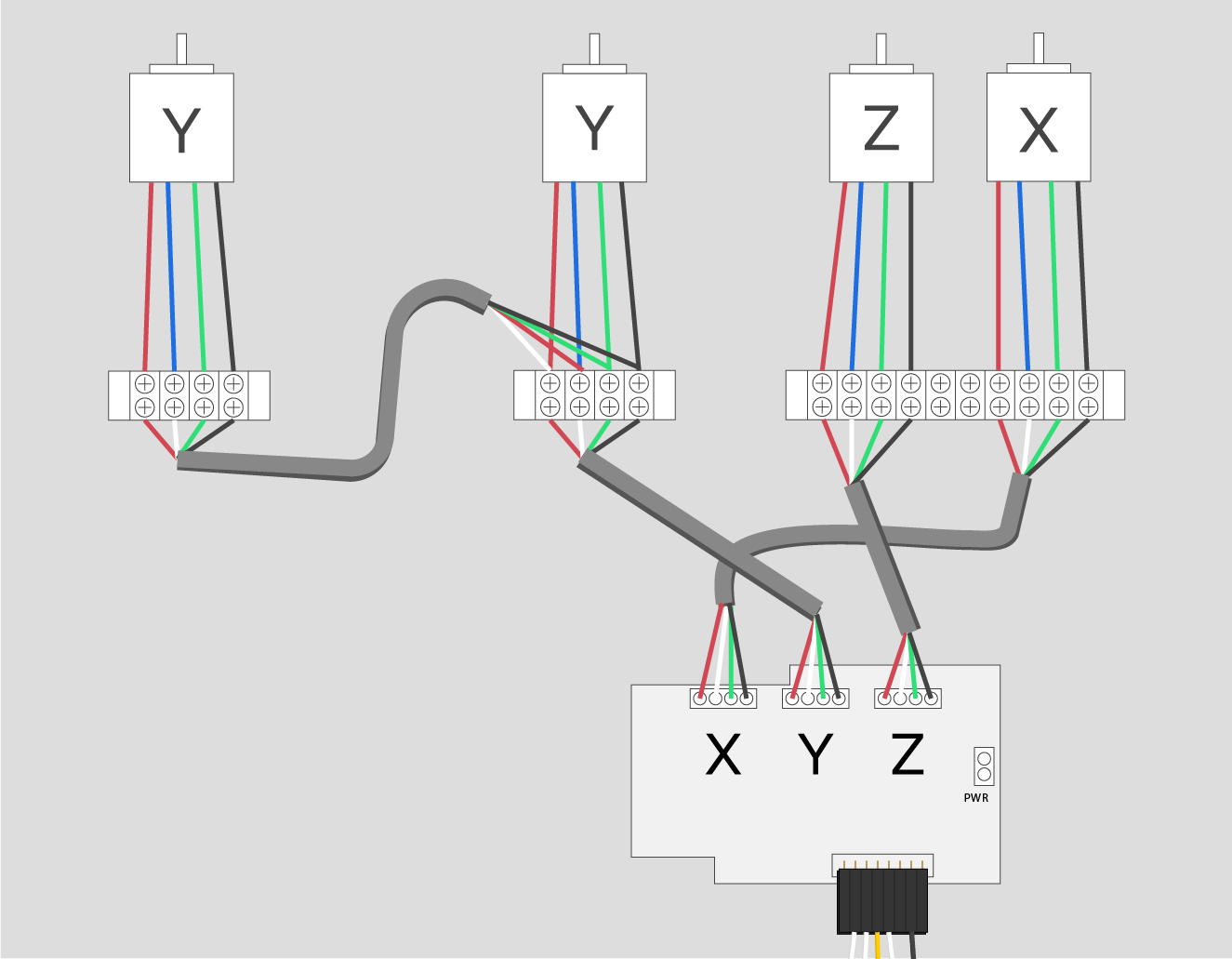
This diagram should help clarify this step, and will be referenced again when you wire your stepper cable to the gShield in the Electronics section.
5. Soldering Limit Switches
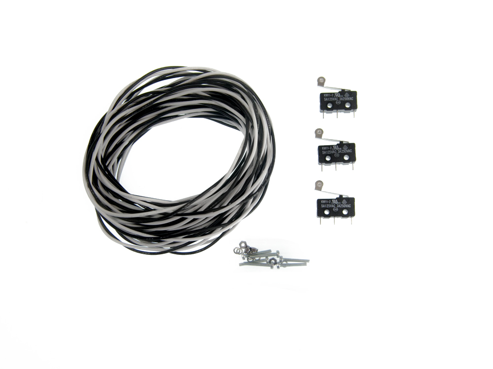
If you purchased a limit switch kit with your X-Carve, click below to solder your limit switches.
Limit Switch
| 500mm Machine | |
| X-Axis | 6 feet |
| Y-Axis | 4 feet |
| Z-Axis | 6 feet |
| 1000mm Machine | |
| X-Axis | 12 feet |
| Y-Axis | 6 feet |
| Z-Axis | 12 feet |
