Z-Axis
| Core Components Kit | ||
| SKU | Name | Quantity |
| 25142-09 | MakerSlide Black 200mm | 1 |
| 30534-01 | Z Axis Motor Plate | 1 |
| 30169-01 | Flanged Bearing 8mm | 1 |
| 25286-17 | Button Head Cap Screw M5 x 8mm | 2 |
| 25286-18 | Button Head Cap Screw M5 x 10mm | 2 |
1. Insert Flanged Bearing
Insert the flanged bearing into the Z-Plate as shown. Be sure to insert the bearing from the side of the plate that has a recession, the bearing will sit inside the hole so that the flange is flush with the Z-Plate.

Insert two small screws to hold the bearing captive. Finger tighten both and check to make sure the flange is flush with the Z-Plate. Then tighten them down with moderate force.


2. Attach the Z-Plate to the Z-Axis Makerslide
Before you attach the Z-Axis Makerslide to the Z-Plate be sure that you have the correct orientation:

Use the two longer button head cap screws to attach the Z-Plate to the Z-Axis Makerslide. The screws go through the Z-Plate and into the Makerslide.

When you’re done your Z-Axis should look like this:

3. Attach the Z-Axis to the X Carriage
| Core Components Kit | ||
| SKU | Name | Quantity |
| 25281-05 | T-Slot Nut M5 Pre-Assembly | 4 |
| 25286-18 | Button Head Cap Screw M5 x 10mm | 4 |
Push two screws through the top Z-Axis mounting holes on the X Carriage.

Thread two insertion nuts onto these screws. You’ll only need a couple of threads to grab.


The backside of the Z-Axis Makerslide has two slots that are designed to accept insertion nuts. Slide these slots over the insertion nuts.

Slide the Z-Axis down along the X Carriage to about here and tighten:

Rock the machine onto its front like this:

Insert two more insertion nuts from the bottom of the Z-Axis and finger tighten two screws into them to secure the Z-Axis Makerslide:


The Z-Axis should be captured by four insertion nuts and screws at this point, but you should still be able to slide it up and down the X Carriage. Slide it so that the insertion nuts are just inside of the Makerslide like this:

Tighten all four screws that capture the Z-Axis. Alternate between screws in an x-pattern to maintain alignment.
Rock the machine back on to its feet again to continue:

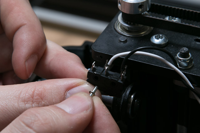
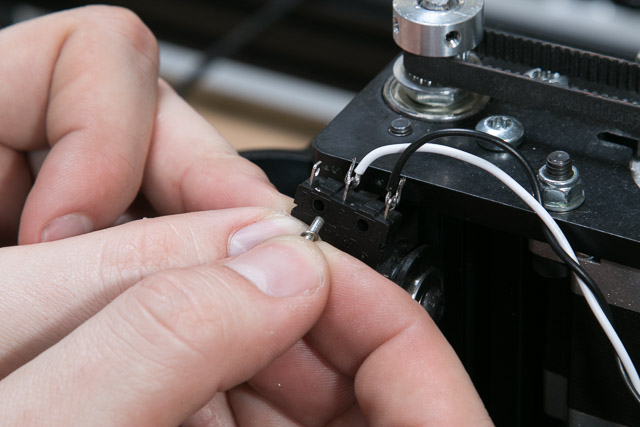
4. Mounting Z-Axis Limit Switch
| Limit Switch Kit | ||
| SKU | Name | Quantity |
| 30557-01 | Microswitch – Roller Actuator | 1 |
| 30544-03 | Pan Head Screw M2 x 10mm | 2 |
| 30555-02 | Split Lock Washer M2 | 2 |
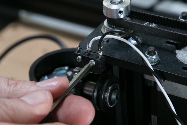
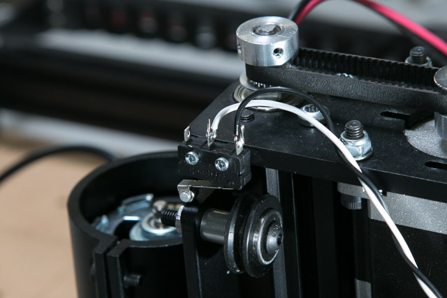
Put the lock washers onto the screws and insert them through the switch and into the holes on the side of the Z-Plate. The holes are threaded, simply tighten the screws just past finger tight.