Gantry
Now it’s time to combine the X Carriage, Y-Plates and X-Axis to form the Gantry. You’ll need these parts:
| Rail Kit | ||
| SKU | Name | Quantity |
| 25142-10 | MakerSlide Black | 1 |
| 25142-10 | MakerSlide Black with X-Carve Logo | 1 |
| Core Components Kit | ||
| SKU | Name | Quantity |
| 25286-18 | Button Head Cap Screw M5 x 10mm | 8 |
| 25287-08 | Flat Washer M5 | 4 |
| 25281-05 | T-Slot Nut M5 Pre-Assembly (Insertion Nut) | 2 |
| X Carriage Assembly | 1 | |
| Y-Plate Assembly | 2 | |
X-CARVE UPDATE
Kits are now shipping with pre-tapped Makerslide.
Thread forming/self tapping screws are no longer being used, and have been replaced with button head cap screws. Images still show the thread forming screws and will be updated soon.
Some kits may include M5 × 12mm button head cap screws, qty 18. These replace the self-tapping screws used to connect Makerslide to its respective plates, and are interchangeable with the M5 × 10mm button head cap screws.
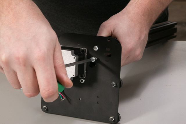
1. Attach the Makerslide to the Right Y Motor Plate

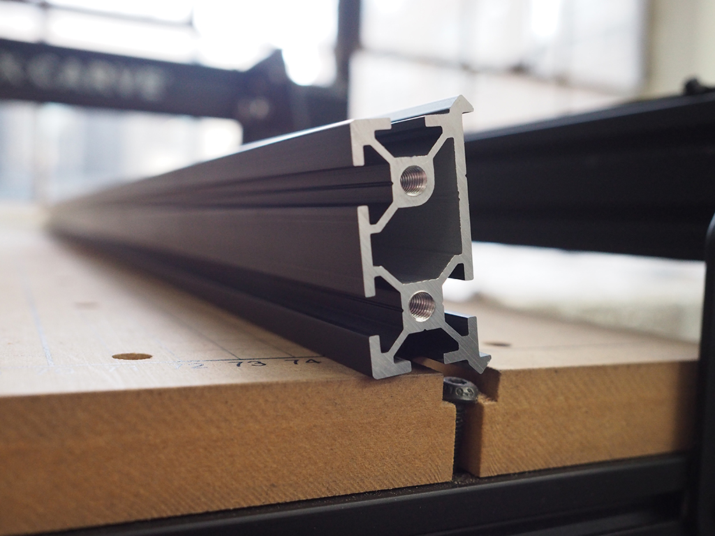
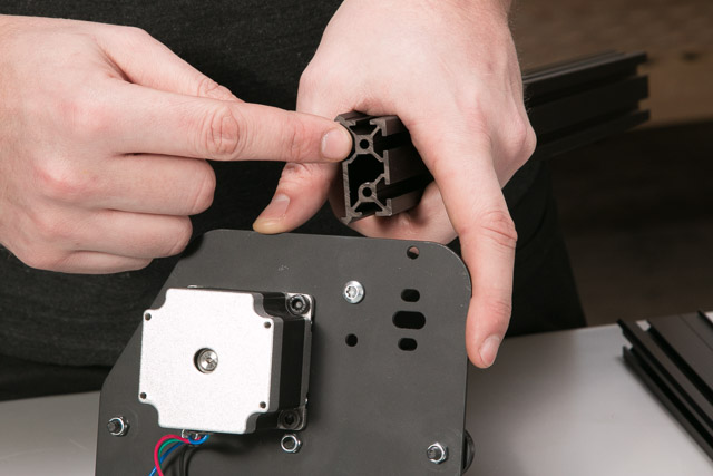
You’ll be using two pieces of Makerslide to create an X-Axis. Make sure to grab the MakerSlide with the X-Carve logo. The logo will be oriented on the right side of the machine facing front. You’ll start by attaching the right Y-Plate to one piece of Makerslide. Orient the Makerslide and Y-Plate like this:

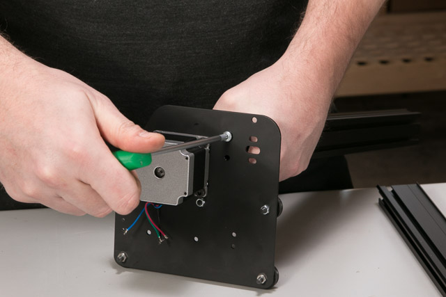
Use the button head cap screws to attach the Makerslide with the plate:
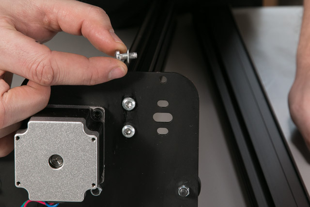
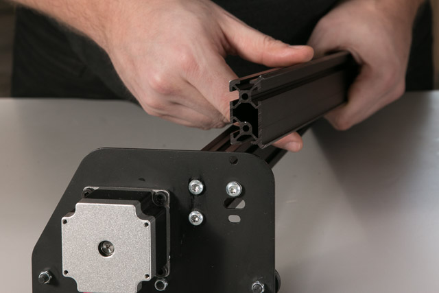
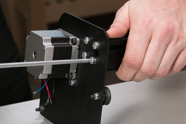
2. Attach the Second Piece of Makerslide
Next you’ll attach another piece of Makerslide to the right Y-Plate with two more button head cap screws and two washers. Notice that these screws will be going through slots, not holes. All screws that are driven through slots on the X-Carve will use washers to distribute the load on the joint. Drive these screws until they are flush with the plate and then back them off a full turn to allow for adjustment in future steps.
If you have limit switches, make sure the slot on the Makerslide is oriented in the upper position. This slot is used to attach the limit switch “actuator” and will not be aligned with the switch if the Makerslide is positioned incorrectly.
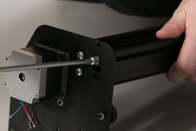
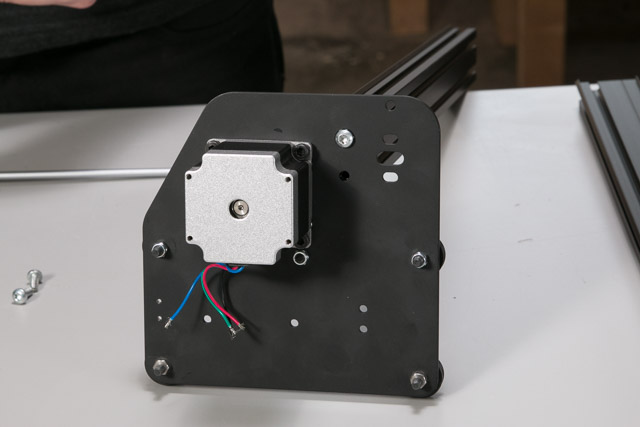
Your X-Axis should look like this:

3. Slide on the X Carriage
Now you’ll slide the X Carriage onto the x-axis. Be gentle with this step as it’s easy to mar the V-Wheels on the sharp edges of the Makerslide if you’re not careful. If you’re finding that the Makerslide doesn’t quite fit in between the V-Wheels check that the eccentric nuts on the X Carriage are in the “open” position. If they are the screws that hold them in place will be as far from the top V-Wheels as possible.

Line up the rails of the X-Axis Makerslide with the V-Wheels of the X Carriage like this:

Slide the X Carriage midway along the X-Axis and set the assembly down.
4. Add Insertion Nuts for Belt Clips
Before you attach the left Y-Plate to the X-axis, slide two insertion nuts into the rear X-axis Makerslide (the one that is closest to the X-Motor). You’ll use these to attach belt clips later.

5. Attach Left Y Motor Plate and Makerslide
Now repeat the process you used to attach the right Y-Plate to the X-axis. You should have an assembly that looks like this when you’re done:
