Electronics
1. Attach the Power Supply to the Power Supply Interface
| Power Supply Kit | ||
| SKU | Name | Quantity |
| 30353-07 | Enclosed Power Supply 24VDC 400W | 1 |
| 30543-01 | Power Supply Interface PCB | 1 |

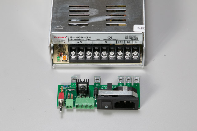
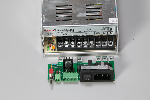
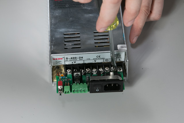
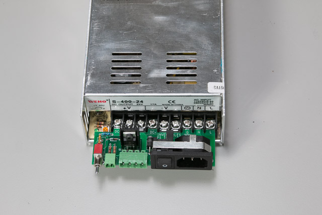
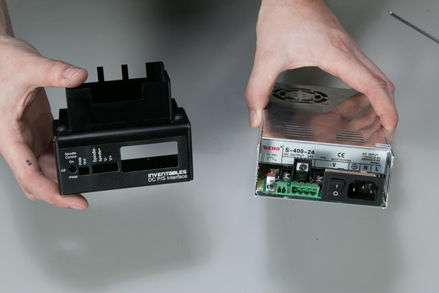
Start by mounting the Power Supply Circuit Board to the Power Supply. You’ll see that the circuit board has fingers that will extend into terminals on the power supply. Hold the circuit board up to the power supply to see which terminals you’ll be using. Remove the screws from each of these terminals and place the power supply circuit board in them. Put the screws back into the terminals through the circuit board and tighten them firmly.

2. Mount gShield Enclosure and P/S Interface
| Power Supply Kit | ||
| SKU | Name | Quantity |
| 30528-01 | Power Supply End Cap | 1 |
| Arduino/gShield Motion Controller Kit | ||
| SKU | Name | Quantity |
| 30560-01 | Electronics Enclosure Base | 1 |
| 25286-18 | Button Head Cap Screw M5 x 10mm | 2 |
| 30265-04 | Nylon Insert Lock Nut M5 | 2 |
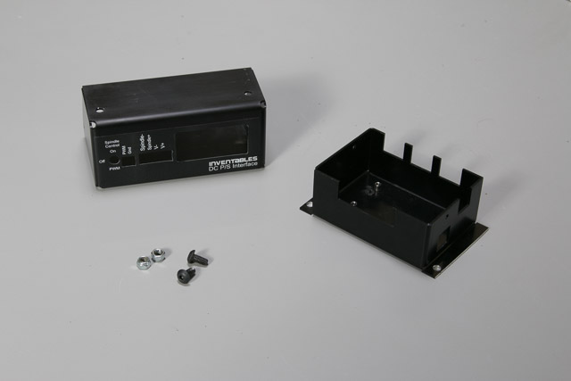
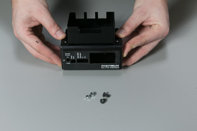
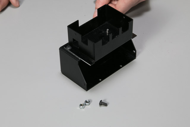
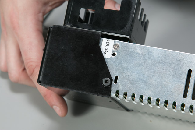
Next you’ll mount the gShield Enclosure to the Power Supply Interface. You’ll put two M5 x 10mm screws into the holes of the gShield Enclosure through the corresponding holes in the Power Supply Interface. Secure them from the inside of the Power Supply Interface with nylock nuts.
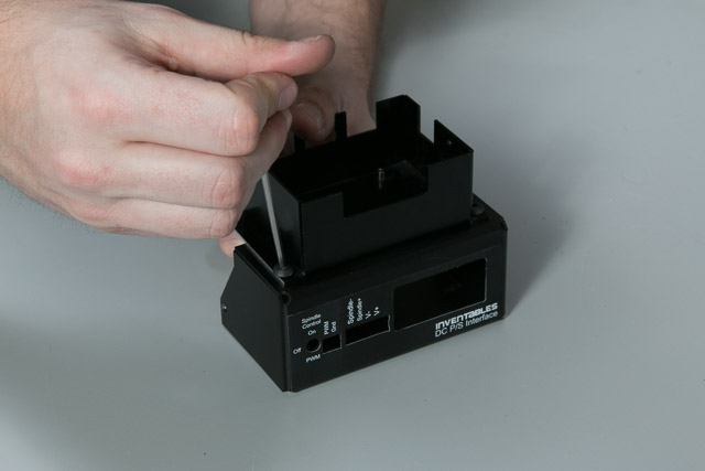
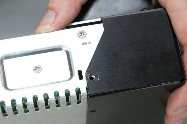
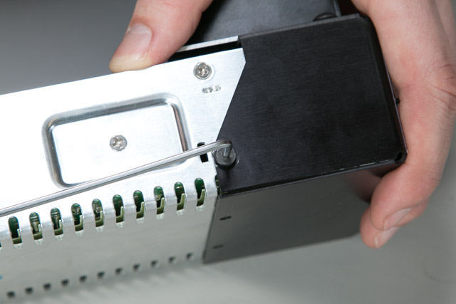
The Power Supply Interface attaches to the Power Supply with four phillips head screws. Slide the interface onto the power supply making sure to push the green terminal blocks through their respective holes. Thread the screws through the interface and into the power supply by hand and then use your wrench to tighten them a little more.
| Power Supply Kit | ||
| SKU | Name | Quantity |
| 25286-23 | Button Head Cap Screw M4 x 5mm | 4 |
| Power Supply Assembly | 1 | |
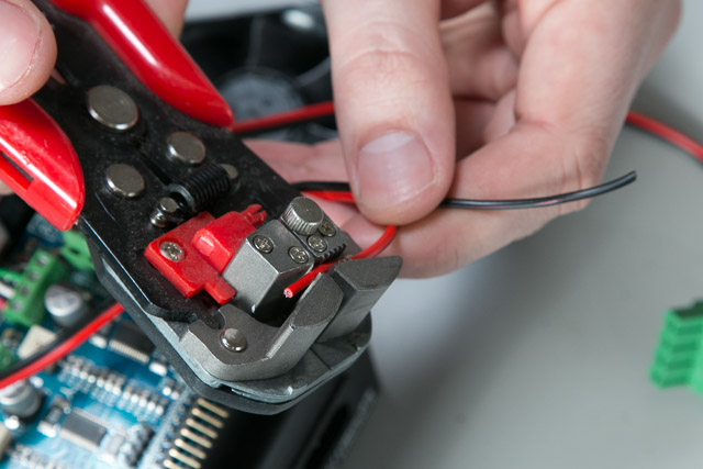
3. Strip the Stepper Cable
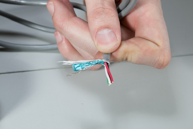
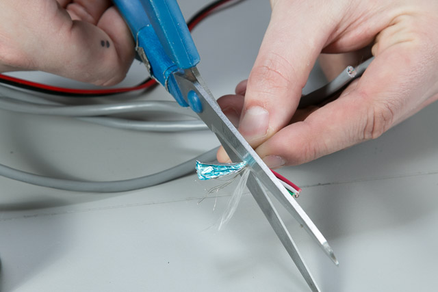
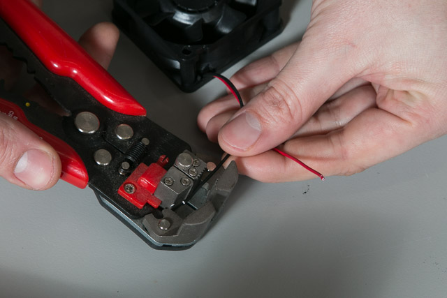
Now for some wiring. Strip about two inches from the end of one piece of stepper cable. You’ll notice that underneath the grey jacket of the stepper cable are foil wrapping, string, a thin raw wire and four colored wires (black, green, white and red). Remove everything except the four colored wires.
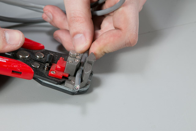
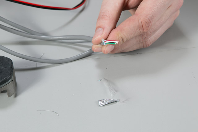
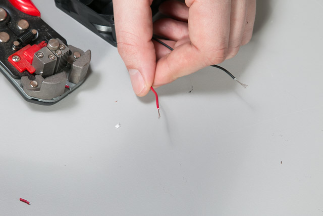
Strip the ends of the four wires about one quarter of an inch.

4. Determine the Axes
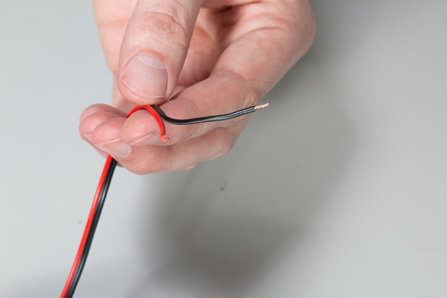
Now twist the copper from the black and green wires together. This will make the stepper motor that the cable is attached to resist movement.

Gently push the X-Axis of your machine in one direction, if the motor feels like it’s resisting your efforts you’ve identified that piece of stepper cable as “X.”

If you don’t feel resistance try moving the Y and Z axes until you find the motor that is resisting movement. If you’re unsure whether or not you’re encountering resistance try untwisting the green and black wires and comparing resistance.


Label the stepper cable as you go.

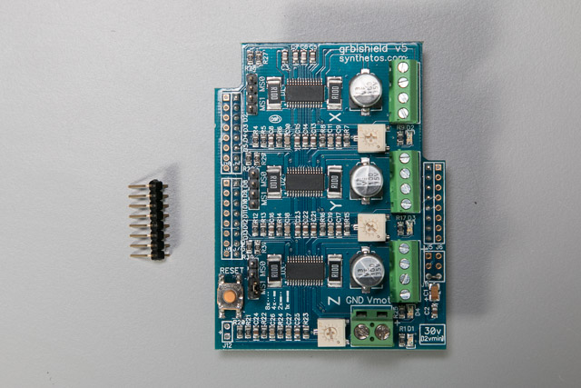
5. Solder Pins to gShield
| Arduino/gShield Motion Controller Kit | ||
| SKU | Name | Quantity |
| 25368-03 | gShield V5 | 1 |
| 30457-05 | Male Header Connector Right Angle 1 × 40 Pins | 1 |
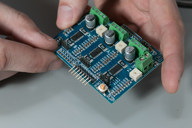
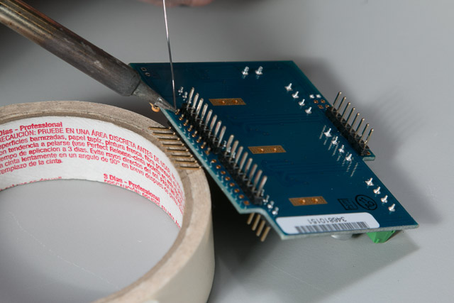
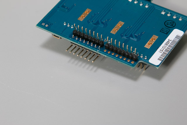
Place the pins into the gShield making sure that the black plastic touches the top of the board. Solder each pin individually making sure to not “bridge” the pins by soldering them together. You may find it easier to solder the pins if you support them with a small object.
 </p>
</p>
6. Wire the Stepper Cable to the gShield
Once you’ve determined which stepper cable belongs to which axis you can wire them into the gShield. First loosen all of the screws on the gShield (they will jump a thread when they are fully loose, but they won’t come out of the terminal blocks.)

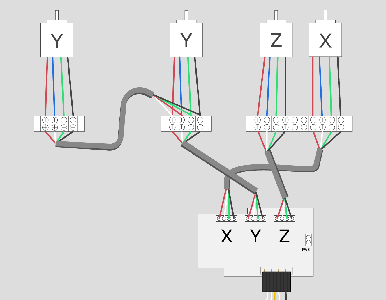
The gShield is marked “X,” “Y,” and “Z.” Wire the stepper cable according to the markings on the shield and order your wires (from left to right) black, green, white, red.

Check out this diagram for clarification.
7. Mount the Arduino
| Arduino/gShield Motion Controller Kit | ||
| SKU | Name | Quantity |
| 25063-03 | Arduino Uno w/ Grbl CNC | 1 |
| 25285-30 | Socket Head Cap Screw M3 x 6mm | 3 |
| Power Supply Assembly | 1 | |
Now grab your Arduino and mount it in the gShield Enclosure. You’ll use three of its four mounting holes to do so.

Push the USB port through the square hole on the gShield enclosure and line up the screws with the threaded inserts on the gShield Enclosure. Screw the Arduino down to the enclosure remembering to alternate screws as you tighten to keep the board even. There’s no reason to go past finger tight with these.

8. Mount the gShield
| Arduino/gShield Motion Controller Kit | ||
| SKU | Name | Quantity |
| 25368-03 | gShield V5 | 1 |
| Power Supply Assembly | 1 | |
Now push the gShield onto the Arduino. There are pins on the gShield that go into the headers of the Arduino. Route the stepper cables out of the three square holes as you do this.

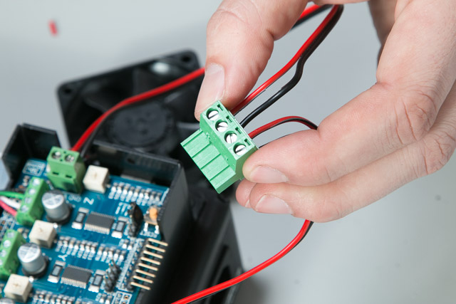
9. Power the gShield and 24V Fan
| Power Supply Kit | ||
| SKU | Name | Quantity |
| 25306-04 | Terminal Block 4C 5mm Plug | 1 |
| Arduino/gShield Motion Controller Kit | ||
| SKU | Name | Quantity |
| 25310-03 | 24V Fan 60mm x 60mm x 25mm | 1 |
| 30461-02 | Zip Wire Blk/Red 18AWG | 1 (foot) |
| Power Supply Assembly | 1 | |
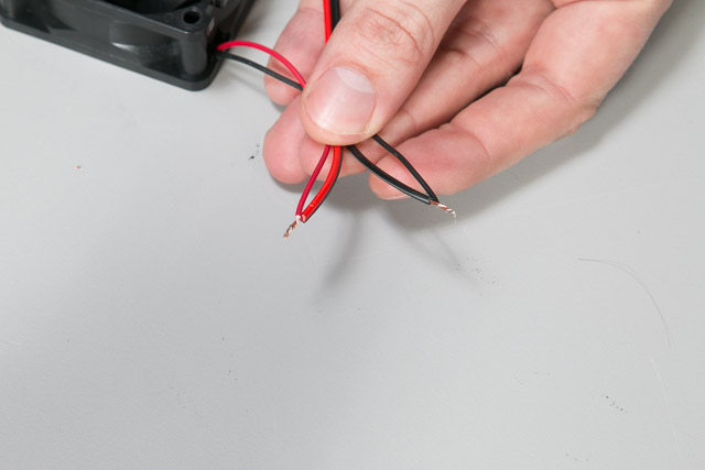
Now strip the zip wire on one end and strip the 24V fan’s wires. Twist the black wires together and then twist the red wires together.
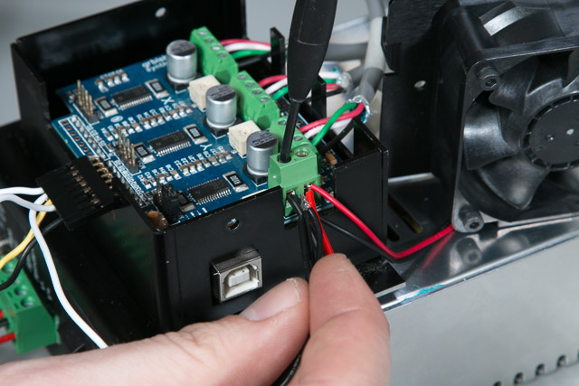
Loosen the screws in the power terminal of the gShield and insert the red twisted pair into Vmot and the black twisted pair into Gnd.

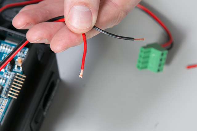
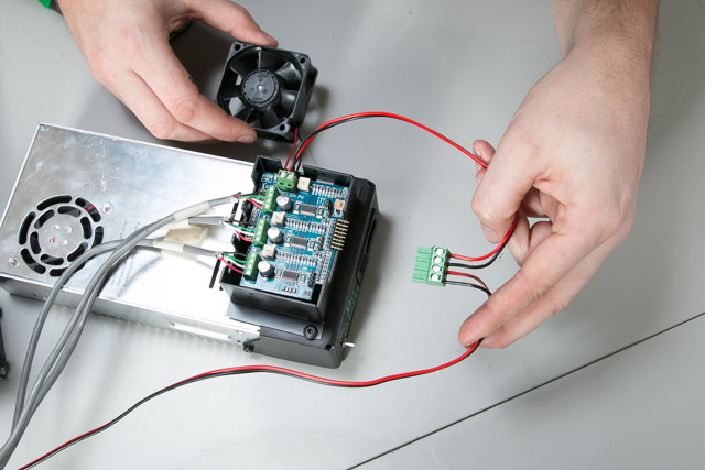
Strip the other end of the zip wire and insert the ends into the large green terminal on the Power Supply Interface.

10. Power the 24V Spindle
Strip the zip wire from your spindle and put the ends into the remaining spots on the large green terminal.
 </p>
</p>
11. Install the gShield Enclosure cover
| Arduino/gShield Motion Controller Kit | ||
| SKU | Name | Quantity |
| 30559-01 | Electronics Enclosure Cover | 1 |
| 25285-30 | Socket Head Cap Screw M3 x 6mm | 2 |
| Power Supply Assembly | 1 | |
Place the top of the gShield enclosure on to the bottom.

There are two M3 x 6mm screws that couple the top and bottom. Thread them into the enclosure by hand and tighten them just past finger tight with your wrench.

12. Install the 24V Fan
| Arduino/gShield Motion Controller Kit | ||
| SKU | Name | Quantity |
| 25285-42 | Socket Head Cap Screw M3 x 35mm | 4 |
| Power Supply Assembly | 1 | |
Use the four M3 x 35mm screws to attach the 24V fan to the gShield enclosure. The bag containing this hardware may be mislabeled as M3 x 25mm screws, but they are the correct 35mm length and should work without a problem.

13. Connect PWM Spindle Control
| Power Supply Kit | ||
| SKU | Name | Quantity |
| 25306-02 | Terminal Block 2C 3.5mm Plug | 1 |
| Arduino/gShield Motion Controller Kit | ||
| SKU | Name | Quantity |
| 30209-12 | Header Connector 0.100" Female 8 Pins | 1 |
| 30210-03 | Header Crimp Contact 0.100" Female 10 Pins | 2 (pins) |
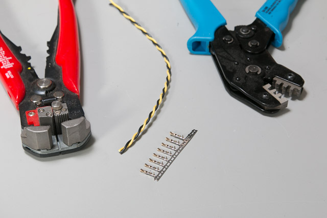
| 30556-02 | Hookup Wire Twisted Blk/Yel 22AWG | 1 (foot) |
| Power Supply Assembly | 1 | |
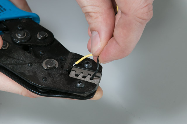
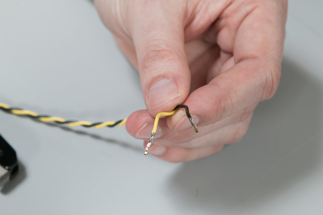
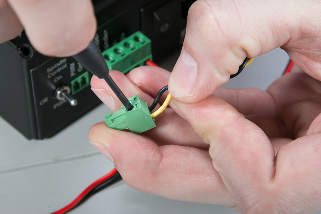
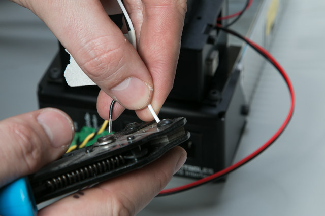
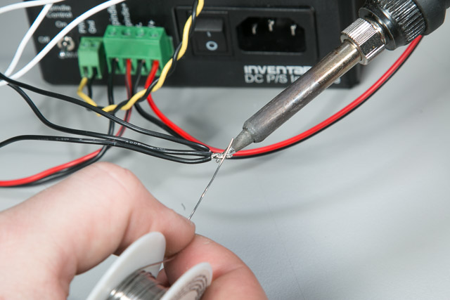
Strip one end of the black and yellow stranded wire. Use the header connectors to see how much jacket to remove. Crimp the header connectors onto the stripped wire ends.
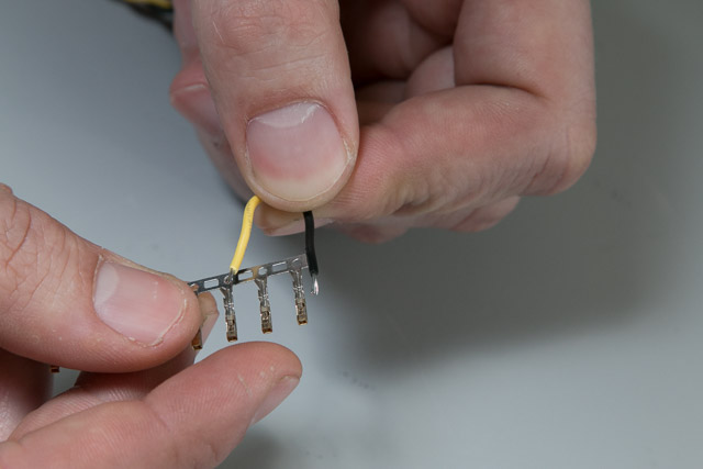
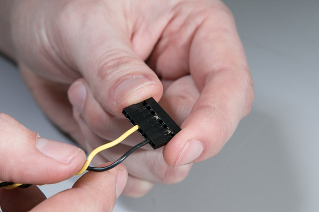
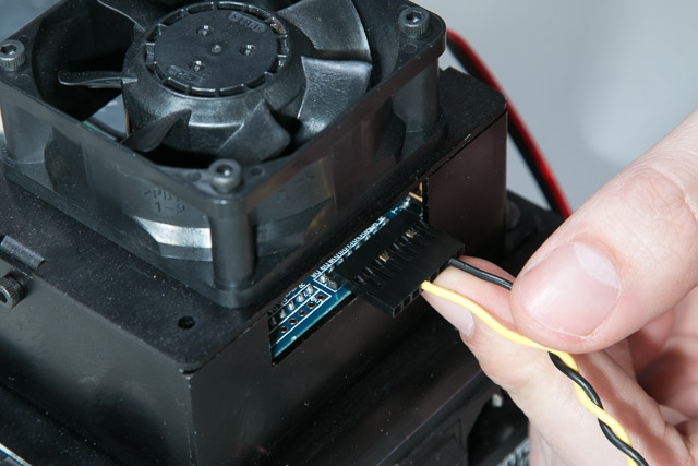
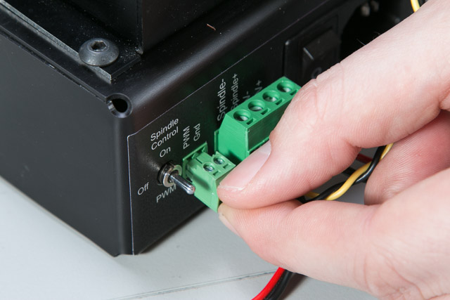
Insert the crimped pins into the header connector as shown. They should click when they are in far enough and you should be able to pull gently on the wire without the pins coming out. Strip the other end of the black and yellow stranded wire. Insert them into the small green terminal block and press it into the Power Supply Interface.
14. Connect Limit Switches to gShield
| Arduino/gShield Motion Controller Kit | ||
| SKU | Name | Quantity |
| 30210-03 | Header Crimp Contact 0.100" Female 10 Pins | 3 (pins) |
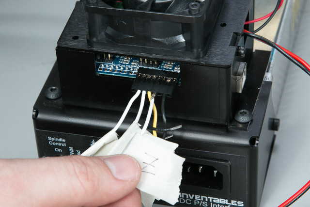
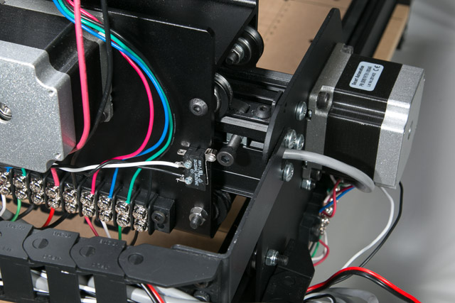
Crimp the white ends of each limit switch wire pair. Insert them into the Header Connector.

The order of the white wires from left to right is X, Y, Z. The first, sixth, and eighth slots are left EMPTY.
Solder the black wires of each pair together and insert them into the GND terminal of the gShield (you will have to temporarily remove the top of the gShield enclosure to do this).
| Limit Switch Kit | ||
| SKU | Name | Quantity |
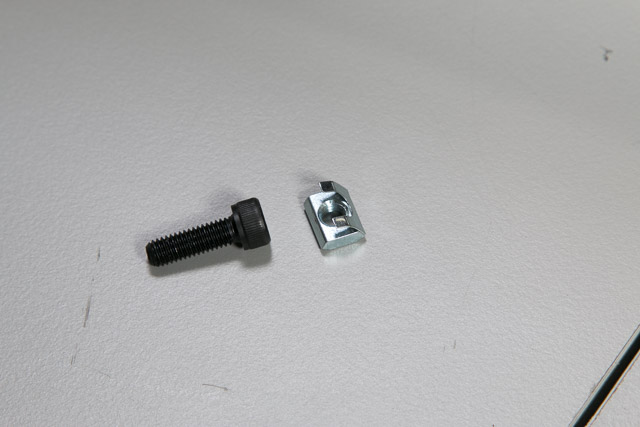
| 25285-36 | Socket Head Cap Screw M5 x 16mm | 2 |
| 26016-03 | T-Slot Nut M5 Post-Assembly (Insertion Nut) | 2 |
Now is a good time to add the “actuators” for the limit switches. Start with the X-Axis limit switch actuator. Push the post assembly insertion nut into the rear piece of X-Axis Makerslide. Screw the M5 screw into the insertion nut. Adjust the placement of the insertion nut by loosening the screw and sliding it left and right. When the actuator is in the right place you’ll be able to activate the switch (you’ll hear a gentle click) without the X Carriage contacting the smooth idlers on the left Y-Plate.
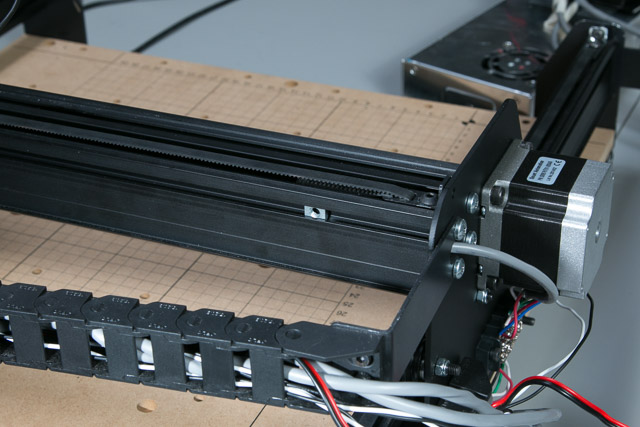
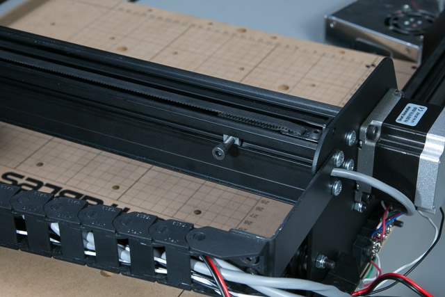
Repeat the process with the Y-Axis limit switch actuator on the left piece of Y-Axis Makerslide.

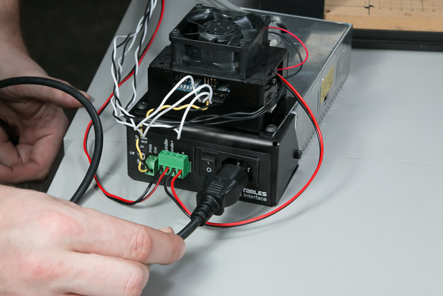
15. Plug in the Electronics Assembly
| Power Supply Kit | ||
| SKU | Name | Quantity |
| 25320-01 | Power Cord EIC320-C13 3ft | 1 |
Now it’s time to plug your Power Supply Assembly into the wall. Make sure both switches on the interface are set to off and double check all of your wiring (especially the placement of red and black wires). If you’ve wired everything correctly, the blue lights on the gShield should light up!