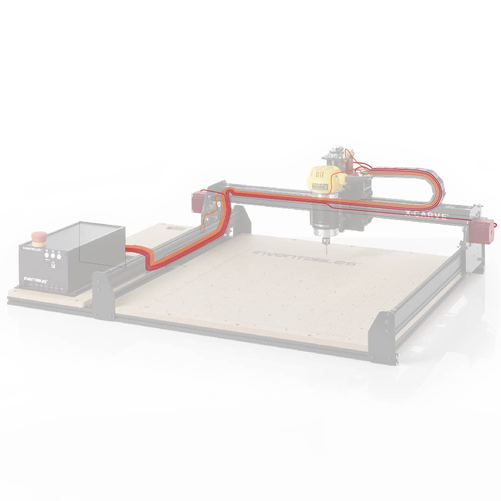
Wiring
| 750mm Motor and Wiring Kit | ||
| SKU | Name | Quantity |
| 30679-05 | Cable Assembly, Stepper Motor 73 in long (X-Axis) | 1 |
| 30679-06 | Cable Assembly, Stepper Motor 34 in long (Y1-Axis) | 1 |
| 30679-07 | Cable Assembly, Stepper Motor 71 in long (Y2-Axis) | 1 |
| 30679-08 | Cable Assembly, Stepper Motor 73 in long (Z-Axis) | 1 |
| 750mm Drag Chain Kit | ||
| SKU | Name | Quantity |
| 30527-06 | Drag Chain Bracket | 1 |
| 30680-01 | Zip Tie Mount | 4 |
| 26016-03 | T-Slot Nut M5 Post-Assembly | 3 |
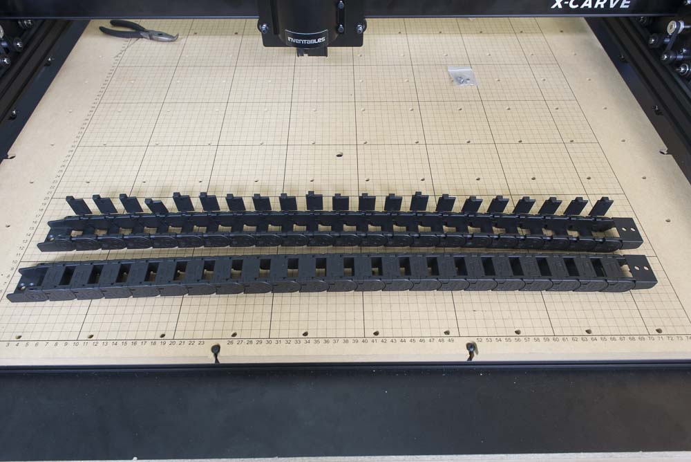
| 30331-12 | Drag Chain 18x25 16 Links w/ Custom Ends | 2 |
| 25986-03 | Cable Tie 4" (100 Pack)25286-44 | 1 |
| 25286-31 | Button Head Cap Screw M5 x 6 | 1 |
| 30554-06 | Flat Head Cap Screw M5 x 10 | 4 |
| 30554-07 | Flat Head Cap Screw M5 x 12 | 6 |
| 30265-10 | Nylon Insert Lock Nut M5 | 6 |
| 750mm Homing Switch Kit | ||
| SKU | Name | Quantity |
| 30682-04 | Cable Assembly, 2C Lugs Ferrules 76"Lg X-Limit | 1 |
| 30682-05 | Cable Assembly, 2C Lugs Ferrules 39"Lg Y-Limit | 1 |
| 30682-06 | Cable Assembly, 2C Lugs Ferrules 76"Lg Z-Limit | 1 |
| Z-Probe | ||
| SKU | Name | Quantity |
| 30611-02 | Z-Probe Kit | 1 |
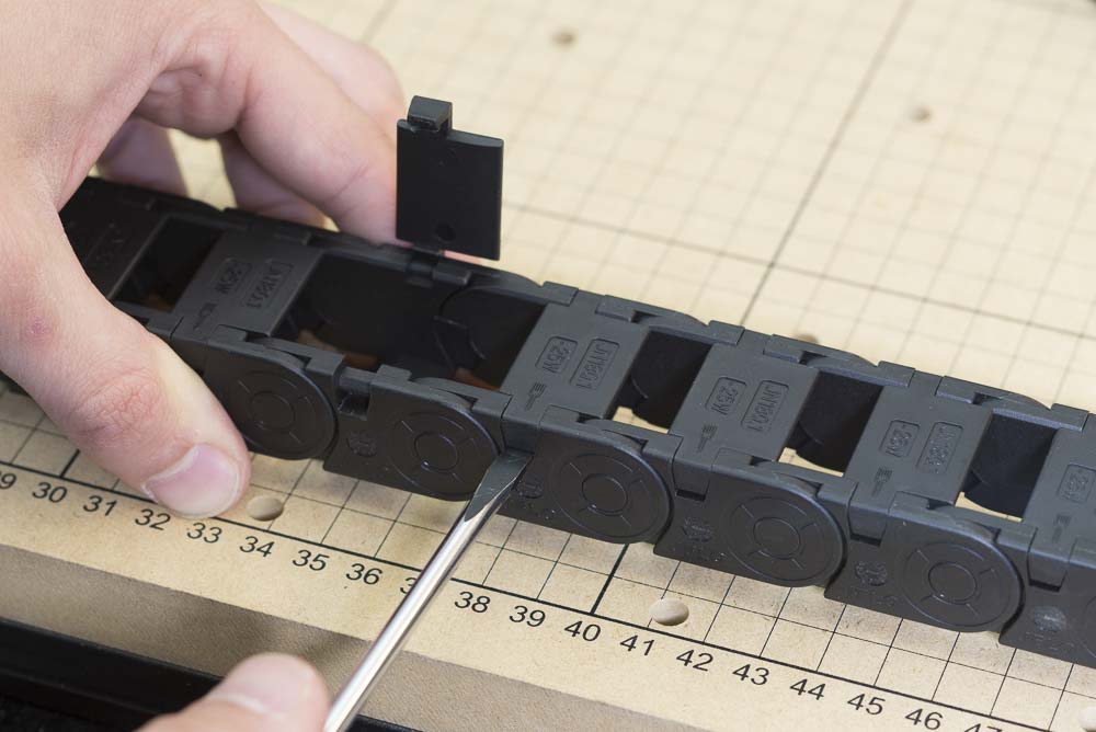
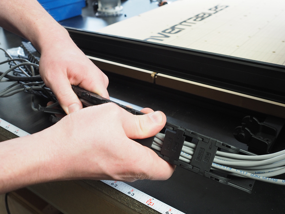
Prepare the drag chain lengths by popping open the hinges using a flat head screw driver.
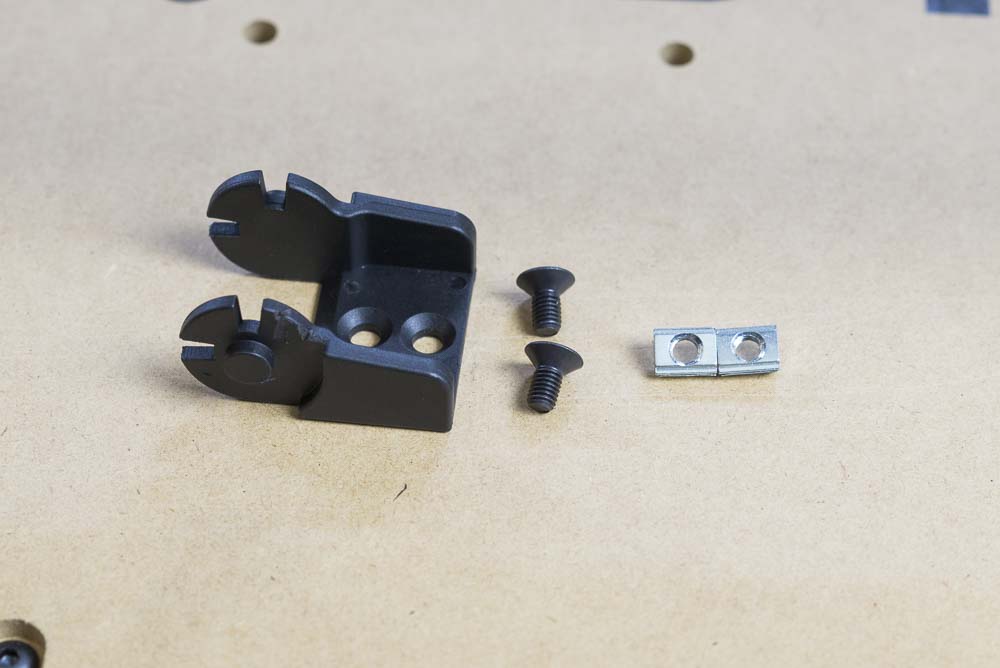
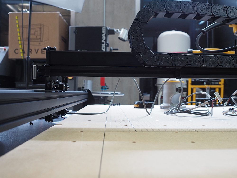
Locate the end of the drag chain, two M5 10mm flat head cap screws, and two post-assembly insertion nuts. Add the post-assembly insertion nuts into the extrusion located behind the wide MakerSlide.
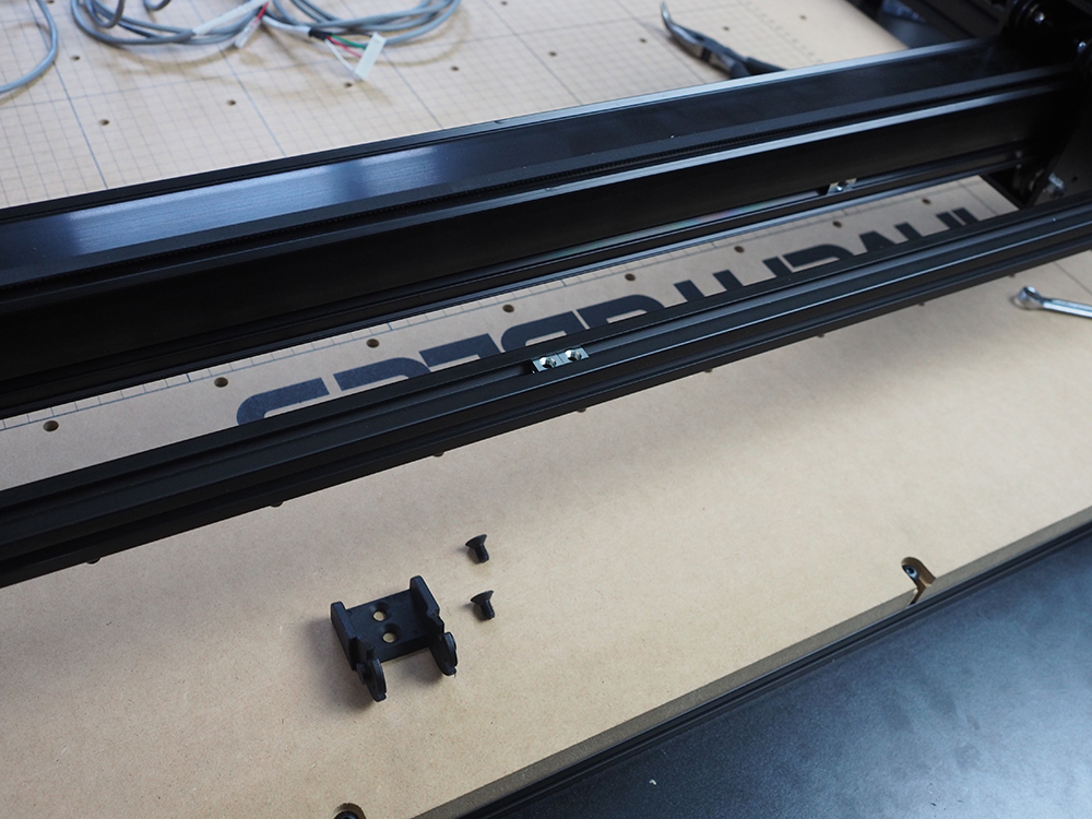
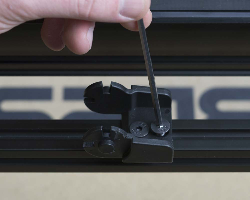
Mount the drag chain end to the extrusion by installing the flat head cap screws into the post-assembly insertion nuts.
Attach Z-Probe (Optional)
If you ordered your machine with a Z-Probe, you can now fasten the Z-Probe barrel connector port and its wire to the x-carriage. However, if you have the dust collector kit, don't attach the barrel connector just yet. You will use an extension bracket that is included with the dust collection kit to attach it in a later step.
First, open your z-probe kit. Set aside the puck and alligator clip wiring harness for the moment; you'll use these to calibrate your machine after it's set up.
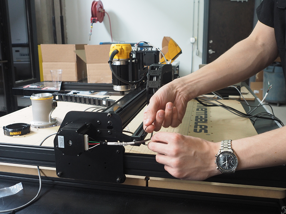
Locate the long wire with the barrel connector port as well as the slim hex nut and lock washer that accompany it.
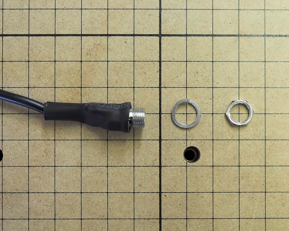
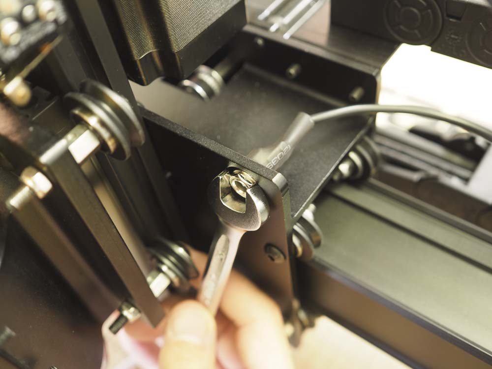
Insert the barrel connector port into the corresponding hole on the top right side of the x-carriage.
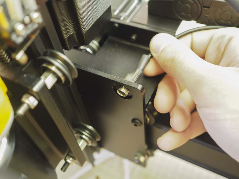
Use a 10mm wrench to secure the port in place, placing first the lock washer and then the hex nut over the port.
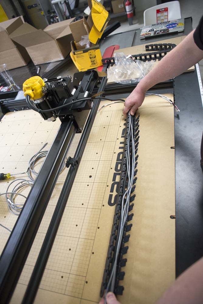
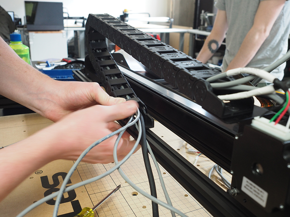
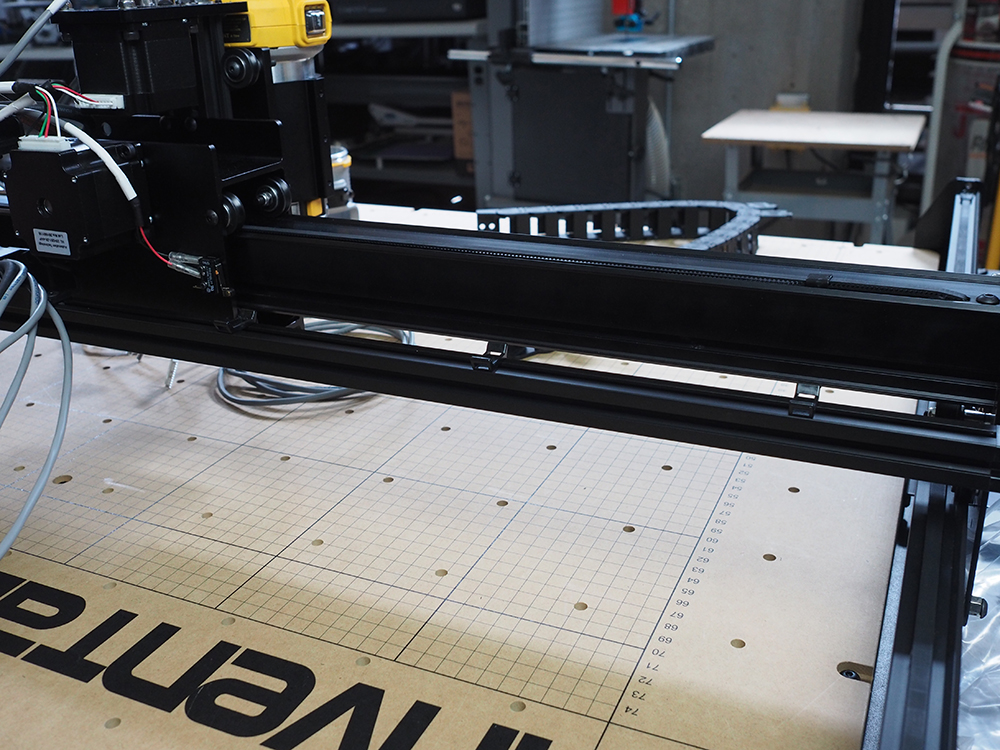
Place the spindle power cord, z-axis stepper motor wire, x-axis stepper motor wire, z-axis limit switch wire, and x-axis limit switch wire into the drag chain. Close up the drag chain hinges.
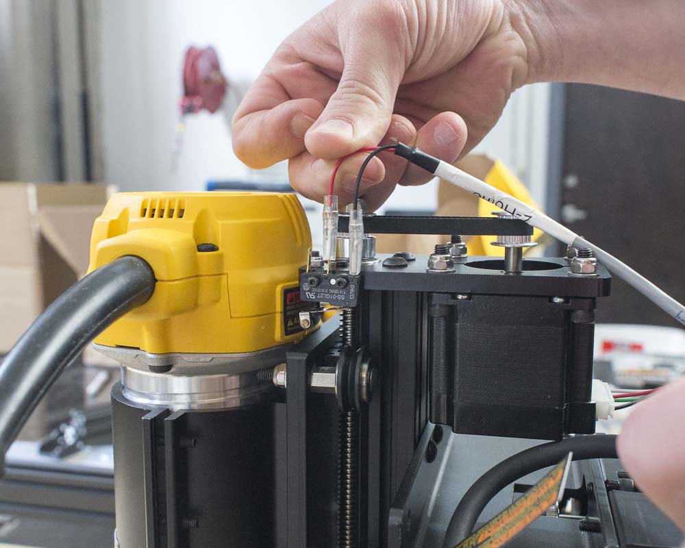
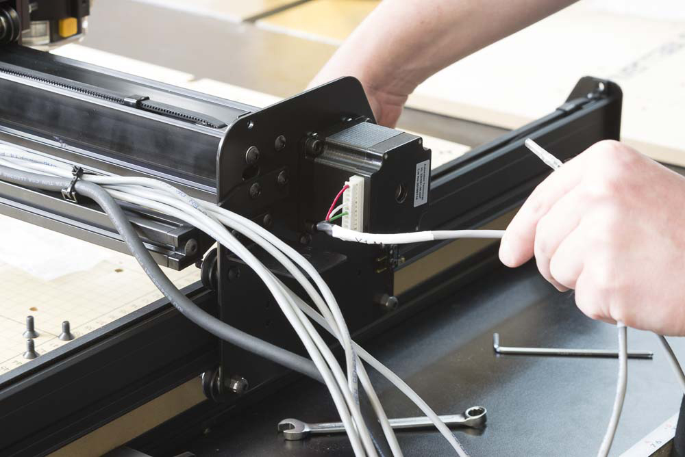
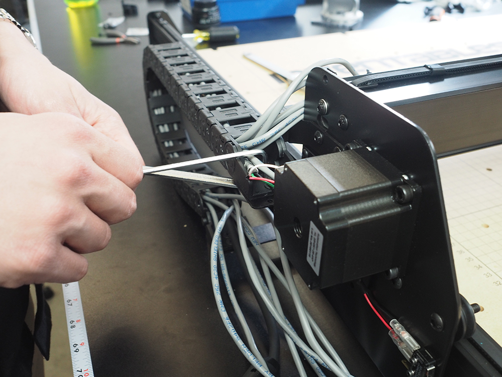
Wire up z-axis and x-axis stepper motors and limit switches. Make sure you attach the red wire to the middle pin and the black wire to the hinged side of the switch. The stepper motors can only be wired in one way, so if it doesn't fit, flip it over and try again.
Attach the drag chain end to the drag chain bracket on the x-carriage.
Attach the length of drag chain to the drag chain bracket installed on the aluminum extrusion.
Try using a screw driver to pry open the length of drag chain. The drag chain end might feel like it's going to break, but it's very hard plastic and should hold up just fine. This might be the most difficult part of the entire build.
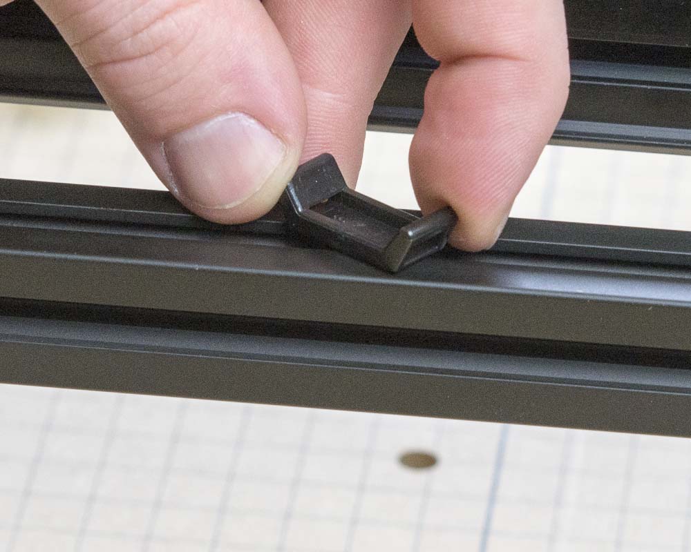
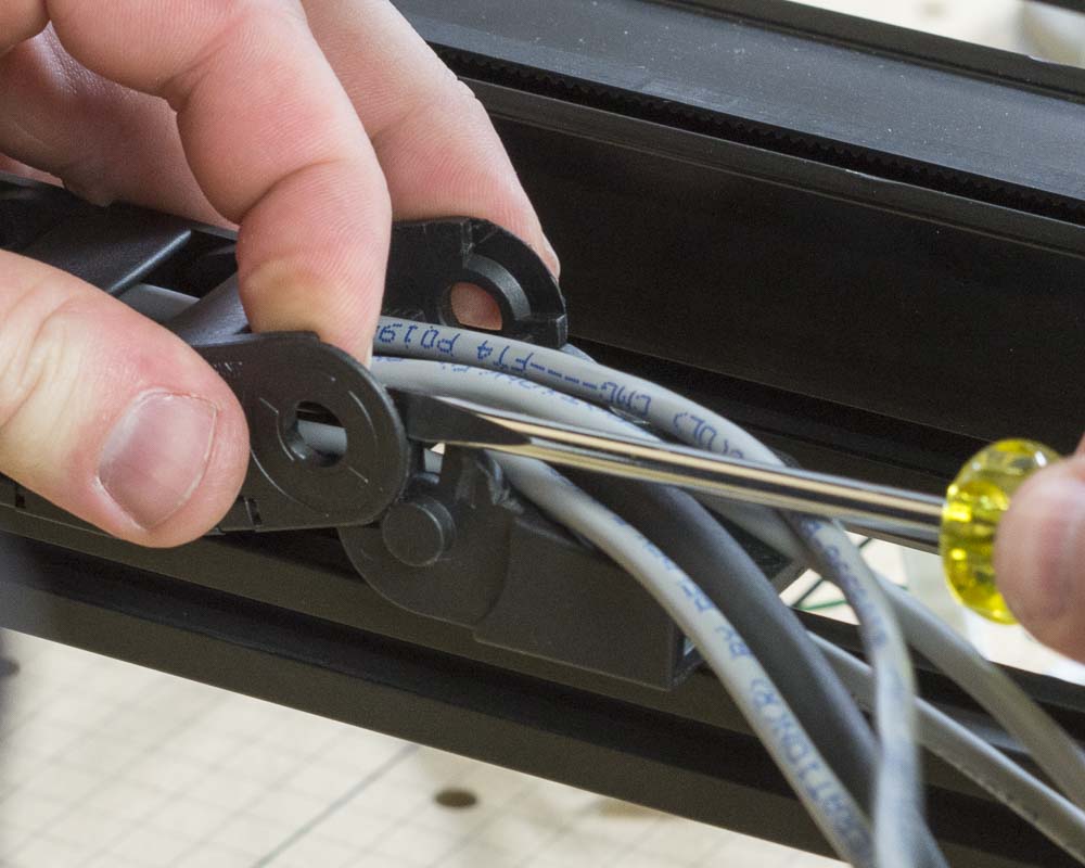
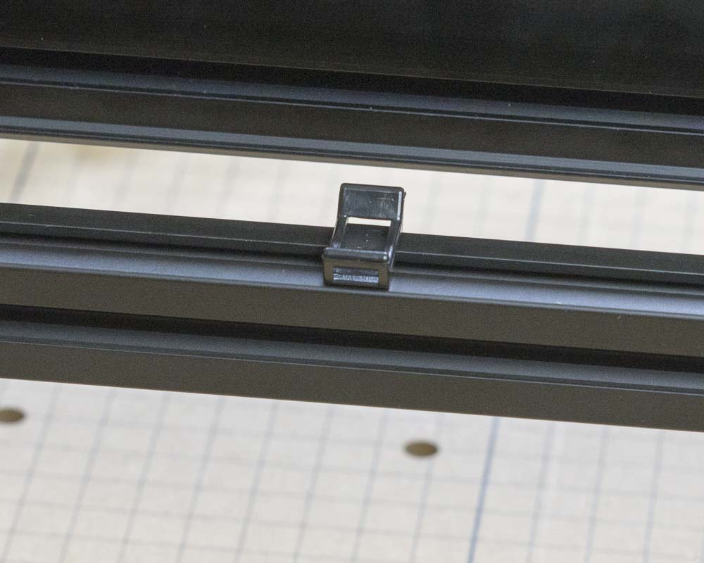
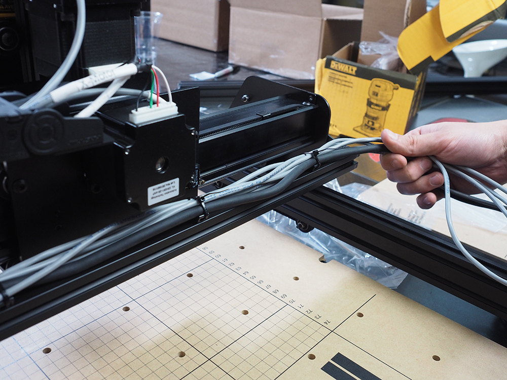
Place the zip tie mounts in the aluminum extrusion slot and rotate them to secure in place.
Use three zip tie mounts on the top of the aluminum extrusion.
Use two zip tie mounts on the side of the aluminum extrusion for the lone Y2 stepper motor.
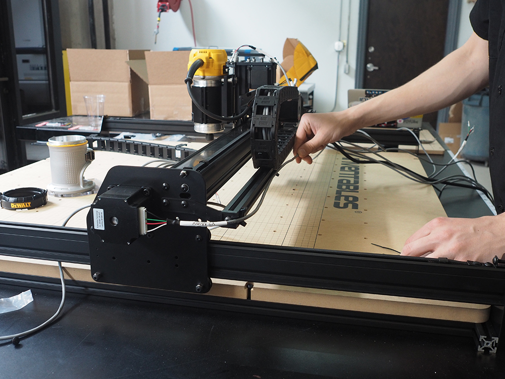
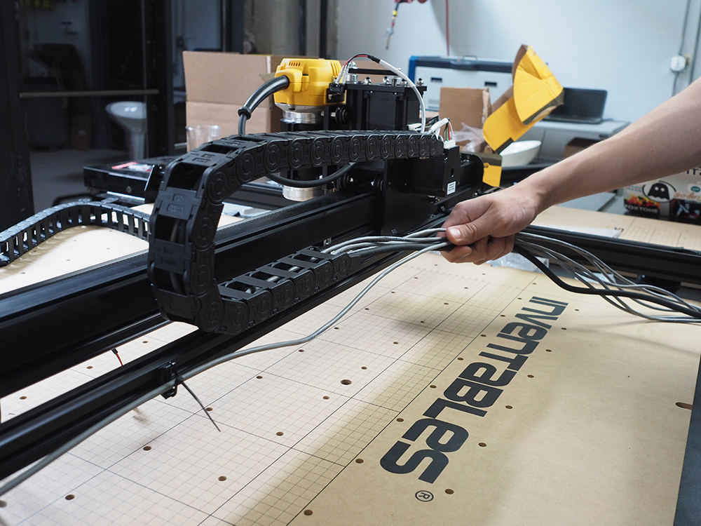
Gather up all the wires from the end of the top drag chain and the Y2 stepper motor. Zip tie them to the zip tie mounts.
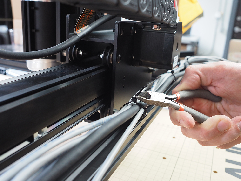
Clip the ends off of the zip ties to clean everything up.
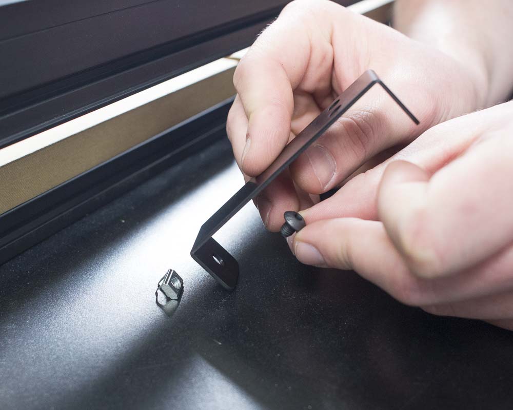
Attach the drag chain bracket to the aluminum extrusion frame using the small button head cap screw and post-assembly insertion nut.
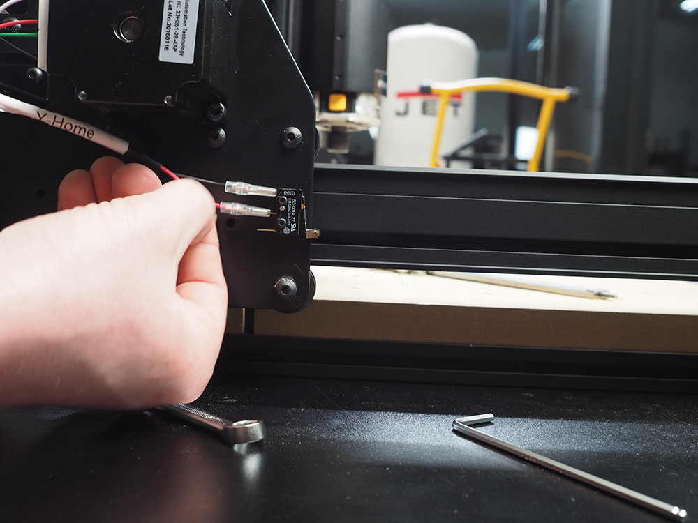
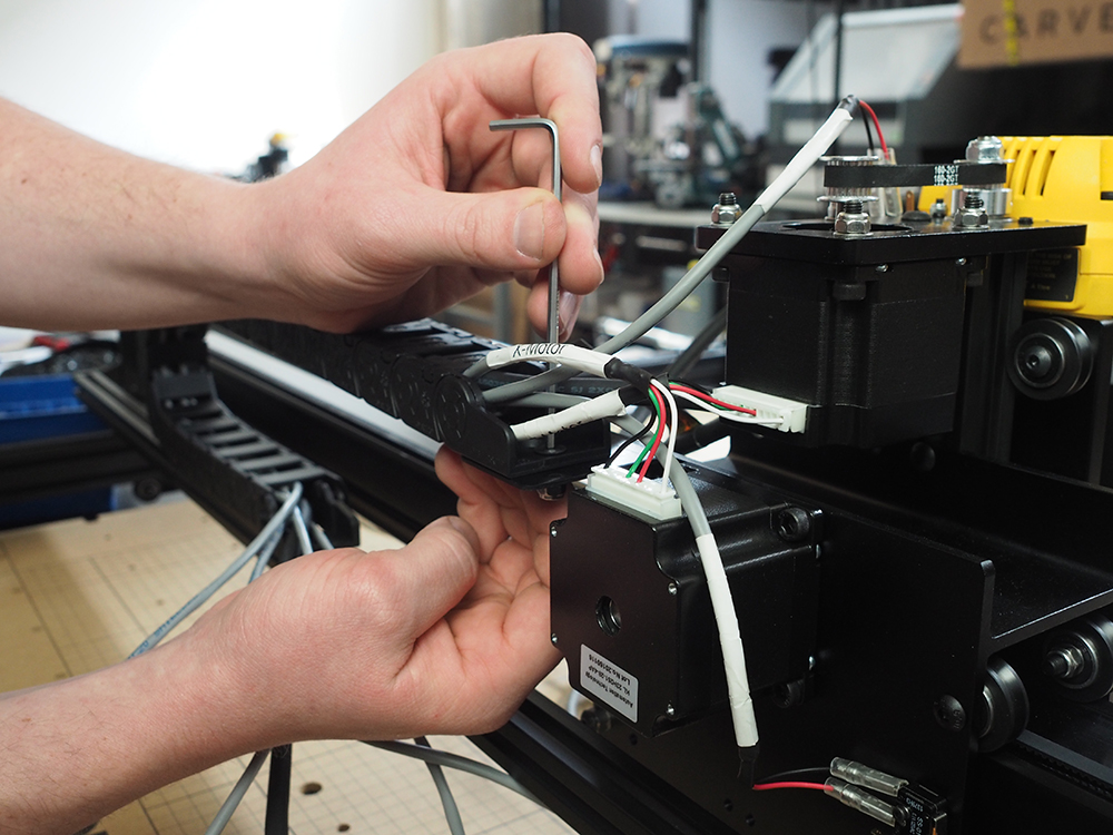
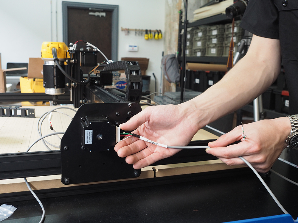
Wire up the Y1 motor and y-axis limit switch.
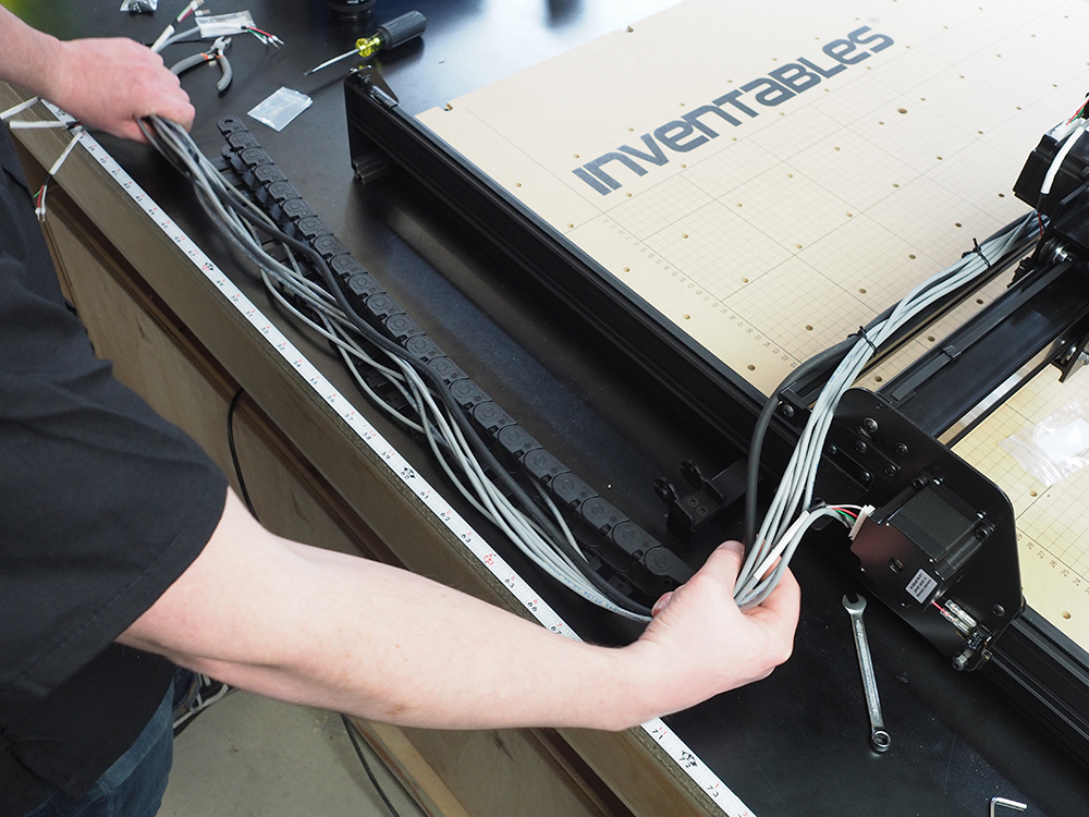
Gather up all wires into the drag chain and snap the hinges in place.
Attach the upper drag chain bracket to the left gantry side plate using two M5 x 12mm Flat Head Cap Screws and two M5 Nylon Insert Lock Nuts. Do not attach the lower drag chain bracket just yet, as that's handled in the next step.
Next Step: Side Board