Calibrate
Note: Many of the mechanical problems you’ll face in the future can be fixed using the following information.
Adjusting the V-Wheels
The first step is to locate the V-Wheels on your fully assembled X-Carve. The V-Wheels are categorized as either fixed or adjustable. The fixed V-Wheels are attached by a regular nylock nut while the adjustable V-Wheels are attached by an eccentric nut. Note that every fixed V-Wheel has an adjustable V-Wheel associated with it. There are 8 V-Wheels on the X Carriage, 4 on each Y-Plate, and 4 on the Spindle Carriage.
After you’ve located the V-Wheels, tighten the fixed V-Wheels on the Machine then adjust the corresponding adjustable V-Wheel. Here you are tightening the adjustable V-Wheel to the point where it takes a little bit of effort for it to spin. (Note: do this slowly to ensure you do not over-tighten the V-Wheel. This can cause the wheels to crack.)
Now repeat this step for every pair of V-Wheels. Finally, test the wheels by moving the carriage. If the wheels moves along with the carriage without much effort, then they are properly tightened. This video demonstrates the concept
Squaring the Z-Axis
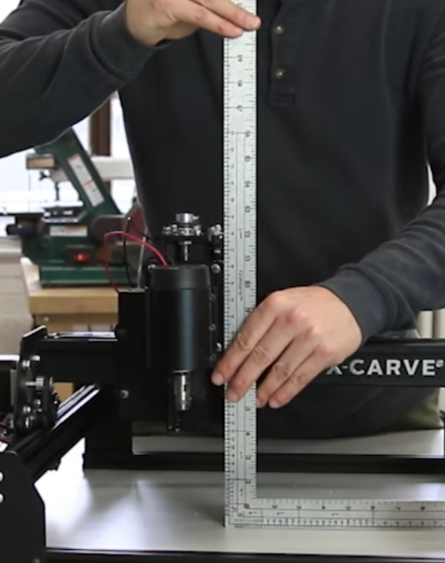
Put the machine on a flat surface and use a large square ruler to see if the Z-Axis is square to the table (as pictured below). If it is not squared, go to the X Carriage and loosen the four button head cap screws that are threaded on the insertion nuts which holds the Z-Axis Makerslide in place (2 on the top and 2 on the bottom). Adjust the Z-Axis until it is square to the table. Once it is squared, retighten the screws and square it one more time to make sure.
Next Step: Computer Setup